Sensor device for distance offset measurements

a technology of distance offset and sensor device, which is applied in the direction of liquid/fluent solid measurement, mechanical measurement arrangement, instruments, etc., can solve the problems of small percentage volume error of such tanks, affecting the accuracy of measurement results, and inability to use tanks, etc., to reduce the angle of radiation received

Active Publication Date: 2021-01-26
SAUDI ARABIAN OIL CO
View PDF17 Cites 0 Cited by
  • Summary
  • Abstract
  • Description
  • Claims
  • Application Information

AI Technical Summary

Benefits of technology

[0009]Embodiments of the present invention provide a sensing device for measuring an offset along a longitudinal axis. The sensing device comprises a housing including a front surface having a plurality of slots, two or more arrays of optical sensors linearly aligned along the longitudinal axis, at least one of the arrays being offset along the longitudinal axis with respect to the other arrays, and a microcontroller coupled to the two or more arrays of optical sensors and configured to determine a positional offset along the longitudinal axis at which light is detected by at least one of the two or more arrays of optical sensors. In some embodiments, each one of the optical sensors of the two or more arrays are positioned within the housing underneath one of the plurality of slots, so as to reduce an angle of incidence of radiation received by the optical sensors of the two or more arrays.
[0010]In certain embodiments, at least some of the plurality of slots are slanted toward the center to further reducing the angle of incidence of radiation received by the optical sensors. It is preferable that the two or more arrays of optical sensors together cover all positions along a span of distance along the longitudinal axis.
[0016]In certain embodiments, each one of the optical sensors of the two or more arrays are positioned within the housing underneath one of the plurality of slots, so as to reduce an angle of incidence of radiation received by the optical sensors of the two or more arrays. At least some of the plurality of slots can be slanted toward the center to further reducing the angle of incidence of radiation received by the optical sensors. It is preferable that the two or more arrays together cover all positions along a span of distance along the longitudinal axis.

Problems solved by technology

A relative small percentage volume error for such tanks can translate into a considerable error in terms of oil barrel volume.
This method is both time consuming and costly, and tanks cannot be in use while the capacity measurements are made.
However, this previous patent does not disclose details concerning a sensor configuration that efficiently accomplishes this task, relying instead on those skilled in the art to develop such a sensor.
While tank calibration techniques have made rapid advances, the optical sensors have not yet been optimized for this procedure.

Method used


Image

  • Sensor device for distance offset measurements
  • Sensor device for distance offset measurements
  • Sensor device for distance offset measurements

Examples


Embodiment Construction

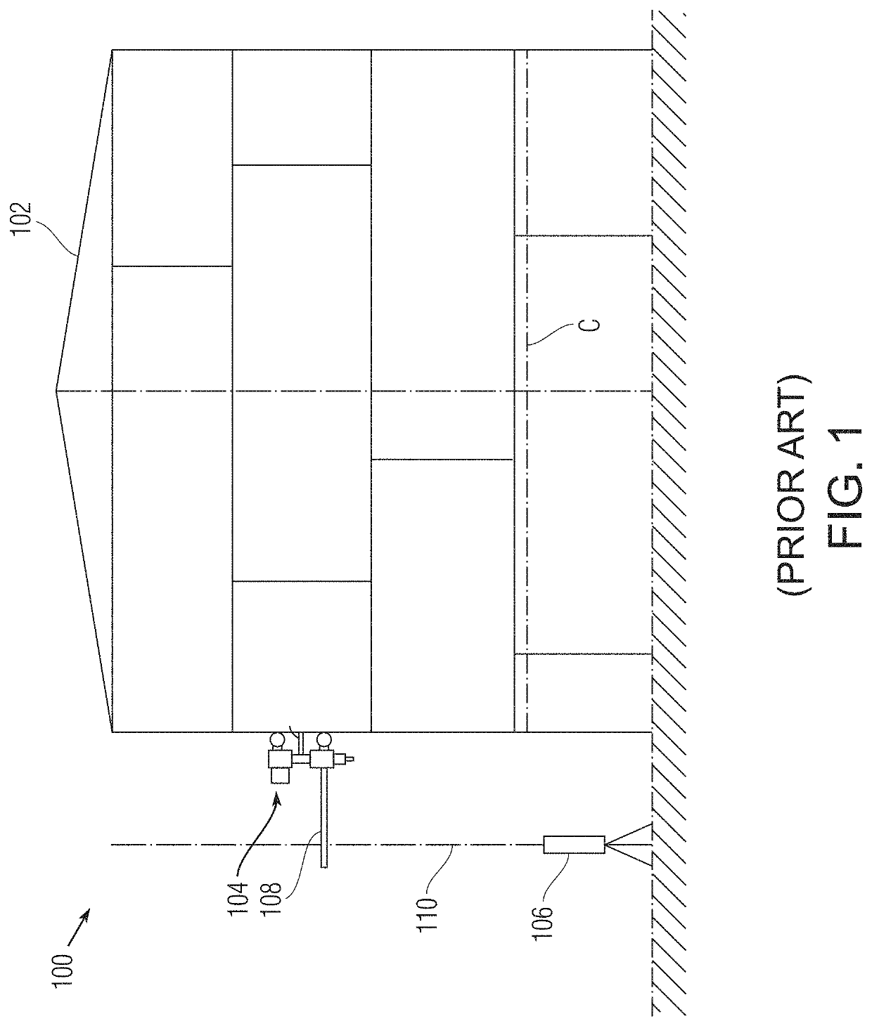
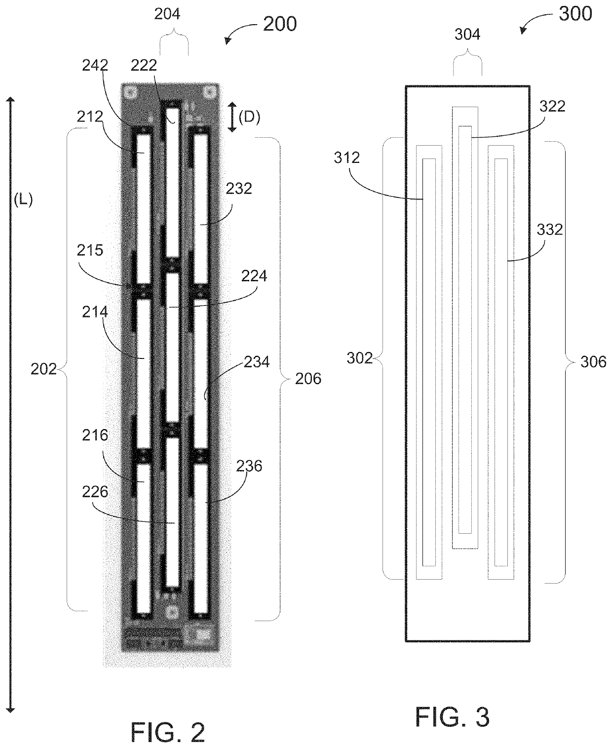
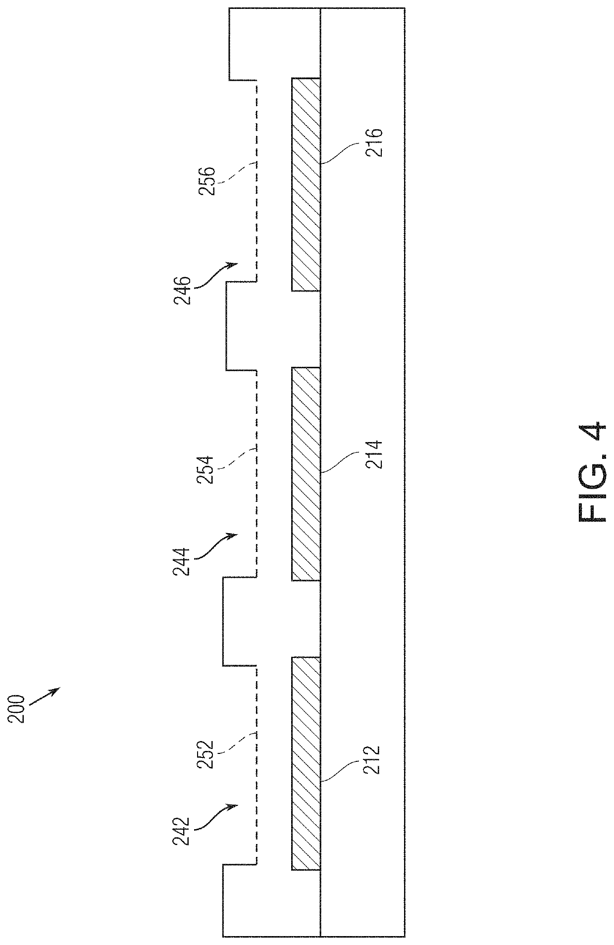
[0029]Embodiments of the present invention provide a sensing device that includes linear arrays of optical sensors which are adjacent to one another and offset with respect to each other along a longitudinal axis. In certain embodiments, the optical sensors comprise multiple linear photodiode arrays or similar high resolution optical sensors. Due to the offset between adjacent linear arrays, any gaps that occur within the linear arrays, individually, are positioned at different levels along the longitudinal axis. Accordingly, there is an optical sensor positioned to capture light at all longitudinal positions within the span of the sensing device (i.e., all gaps are covered). The sensing device can be positioned relative to a surface by a fixed distance and travel along that surface to provide a proxy measurement for the offset of the surface with respect to other measurements and / or the mechanical offset of the laser and sensing device.

[0030]FIG. 2 is a plan view of a sensing devic...


PUM


Abstract

A sensing device for measuring an offset along a longitudinal axis comprises a housing including a plurality of slots, two or more arrays of optical sensors aligned along the longitudinal axis, at least one of the arrays being offset along the longitudinal axis with respect to the other arrays and a microcontroller coupled to the two or more arrays of optical sensors and configured to determine a positional offset along the longitudinal axis at which light is detected by at least one of arrays of optical sensors. In some embodiments, each of the optical sensors of the arrays are positioned within the housing underneath one of the plurality of slots to reduce an angle of incidence of radiation received.

Description

CROSS-REFERENCE TO RELATED APPLICATIONS[0001]The present invention claims priority to U.S. Provisional Patent Application Ser. No. 62 / 626,954, filed Feb. 6, 2018, which is incorporated by reference herein in its entirety.FIELD OF THE INVENTION[0002]The present invention relates to measurement of structural changes to objects including deformation, and in particular relates to a device for measuring offsets for calibration of storage tanks.BACKGROUND OF THE INVENTION[0003]In the oil and gas industry storage tanks are calibrated periodically in order to be able to accurately determine their fuel capacity. This is an important task as some storage tanks are extremely large and can store 2,000,000 barrels or more. A relative small percentage volume error for such tanks can translate into a considerable error in terms of oil barrel volume.[0004]The conventional method of determining tank volume is filling the tank with fluid and then, after reaching capacity, metering the fluid as it is ...

Claims


Application Information

Patent Timeline
Patent Type & Authority Patents(United States)
IPC IPC(8): G01B11/27G01B5/02G01B11/14G01C15/00G01F17/00G01B5/00G01B11/24
CPCG01B11/272G01B5/0021G01B5/025G01B11/14G01B11/24G01C15/006G01F17/00
Inventor PARROTT, BRIANPATEL, SAHEJADABDELLATIF, FADLCARRASCO ZANINI, PABLOAMER, AYMANOUTA, ALIARAB, ABDULLAH
Owner SAUDI ARABIAN OIL CO
Why Eureka
Try Eureka