Joint for high voltage direct current cables

a high-voltage direct current and cable technology, applied in the direction of cable fittings, electrical cable installations, electrical apparatus, etc., can solve the problems of increasing the likelihood of this type of failure, provoking a radial perforation in the cable, and reducing the risk of cable insulating layer perforation

Active Publication Date: 2021-01-26
PRYSMIAN SPA
View PDF26 Cites 1 Cited by
  • Summary
  • Abstract
  • Description
  • Claims
  • Application Information

AI Technical Summary

Benefits of technology

[0014]The Applicant has faced the problem of providing pre-moulded joints for HVDC cable capable of controlling the electric field and space accumulation charge so as to reduce the risk of cable insulating layer perforation.
[0018]While the field grading layer controls the electric field, the deflectors prevent the increasing of the electric gradient around the cable insulating layer, especially at the boundary with the cable outer semiconductive layer. This prevents undesired charge accumulation in the cable insulating layer as well as high electric field inside the cable insulating layer. The risk of perforation is at least remarkably reduced. Therefore, according to a first aspect, the present invention relates to a joint for high voltage direct current cables extending along a longitudinal axis between two opposite end portions, the joint comprising:
[0024]The two deflectors can be positioned and dimensioned so as to longitudinally protrude beyond the joint insulating layer. This configuration of the deflectors eases the handling of the present joint during its installation around the power cables.
[0030]Preferably, the rectangular cross sections of the joint insulating layer and of the joint outer semiconductive layer have substantially the same length. This makes the joint of the invention easy and simple to be manufactured being substantially free from complex geometries that inevitably cause difficulties in the production of the joint and increase its cost.

Problems solved by technology

This causes a charge accumulation which can provoke a radial perforation in the cable and / or in the joint insulation layer.
The likelihood of this type of failures increases as the voltage level increases, and it becomes more likely for HV systems at 320 kV or higher.
To this aim the conventional approach of geometric field control, currently used in AC joints, is not sufficient in DC systems.

Method used


Image

  • Joint for high voltage direct current cables
  • Joint for high voltage direct current cables
  • Joint for high voltage direct current cables

Examples


Embodiment Construction

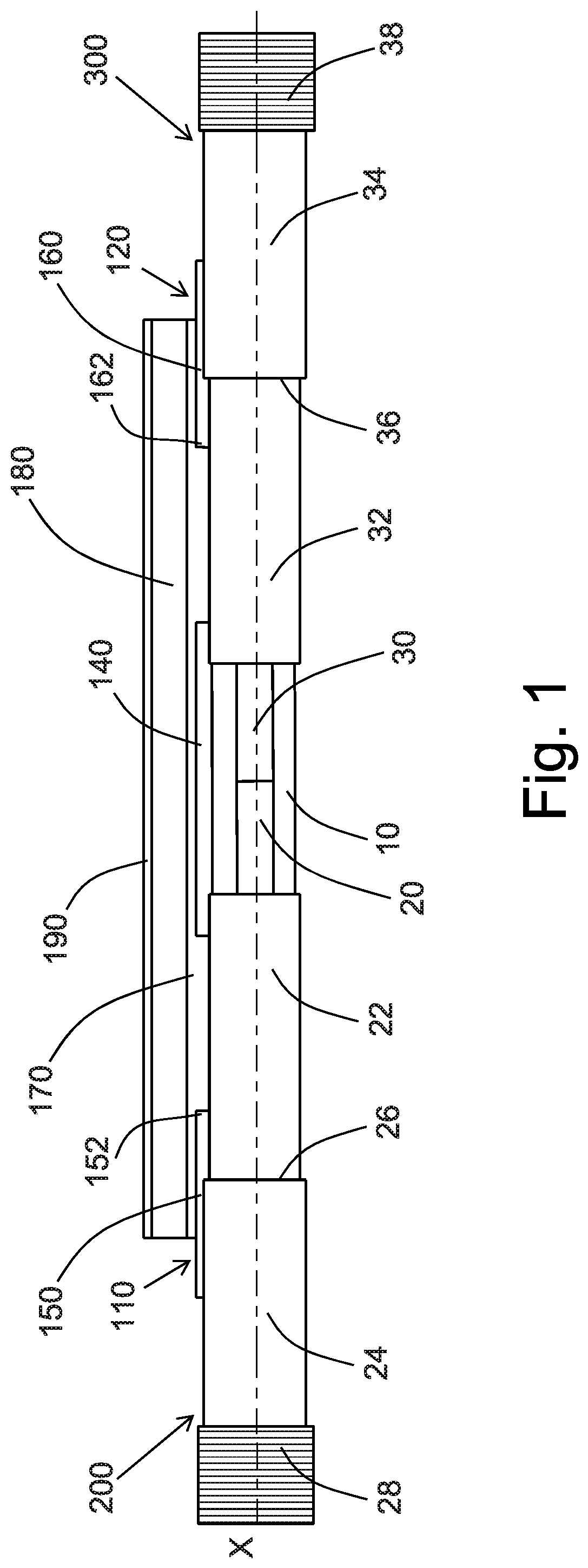
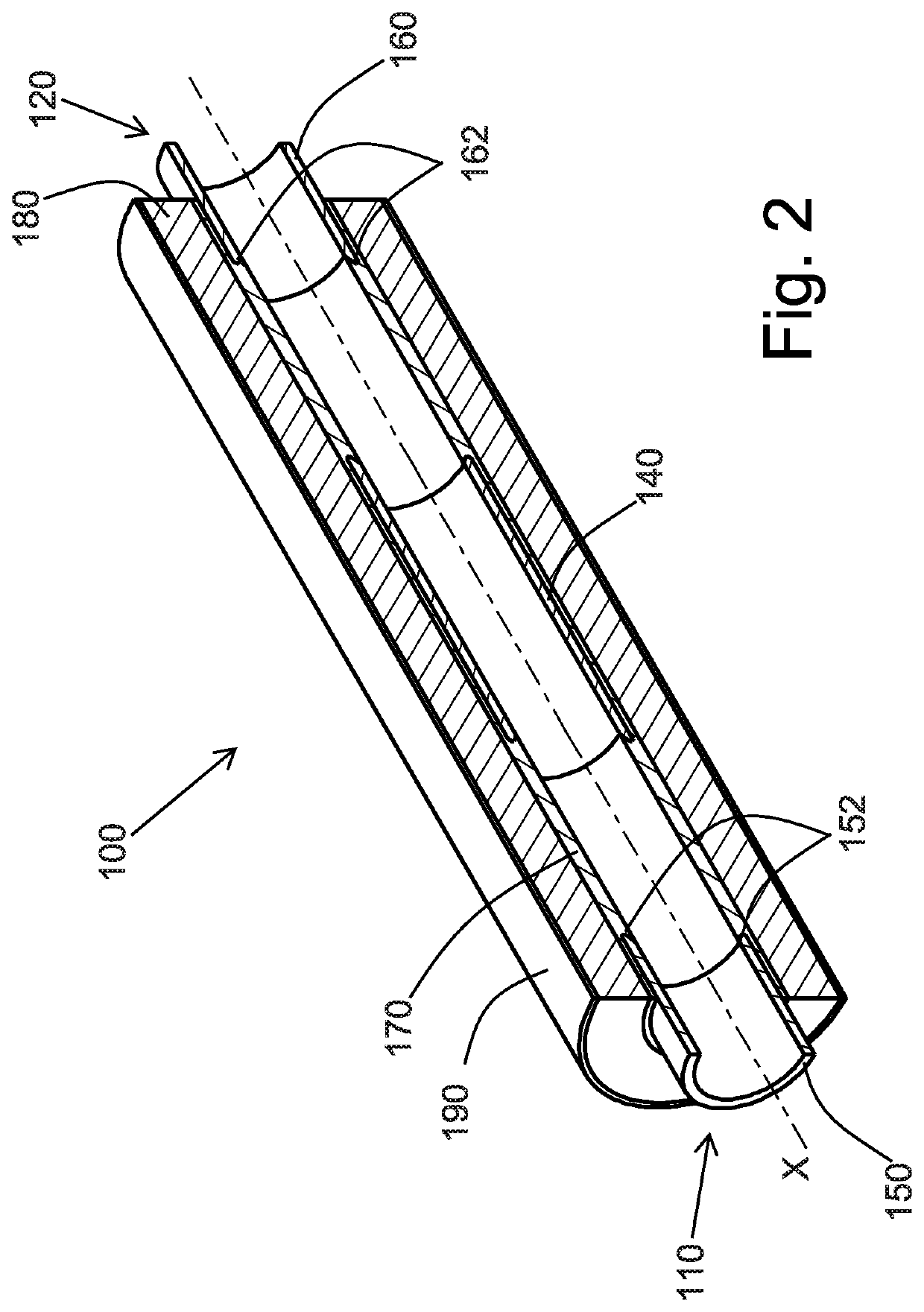
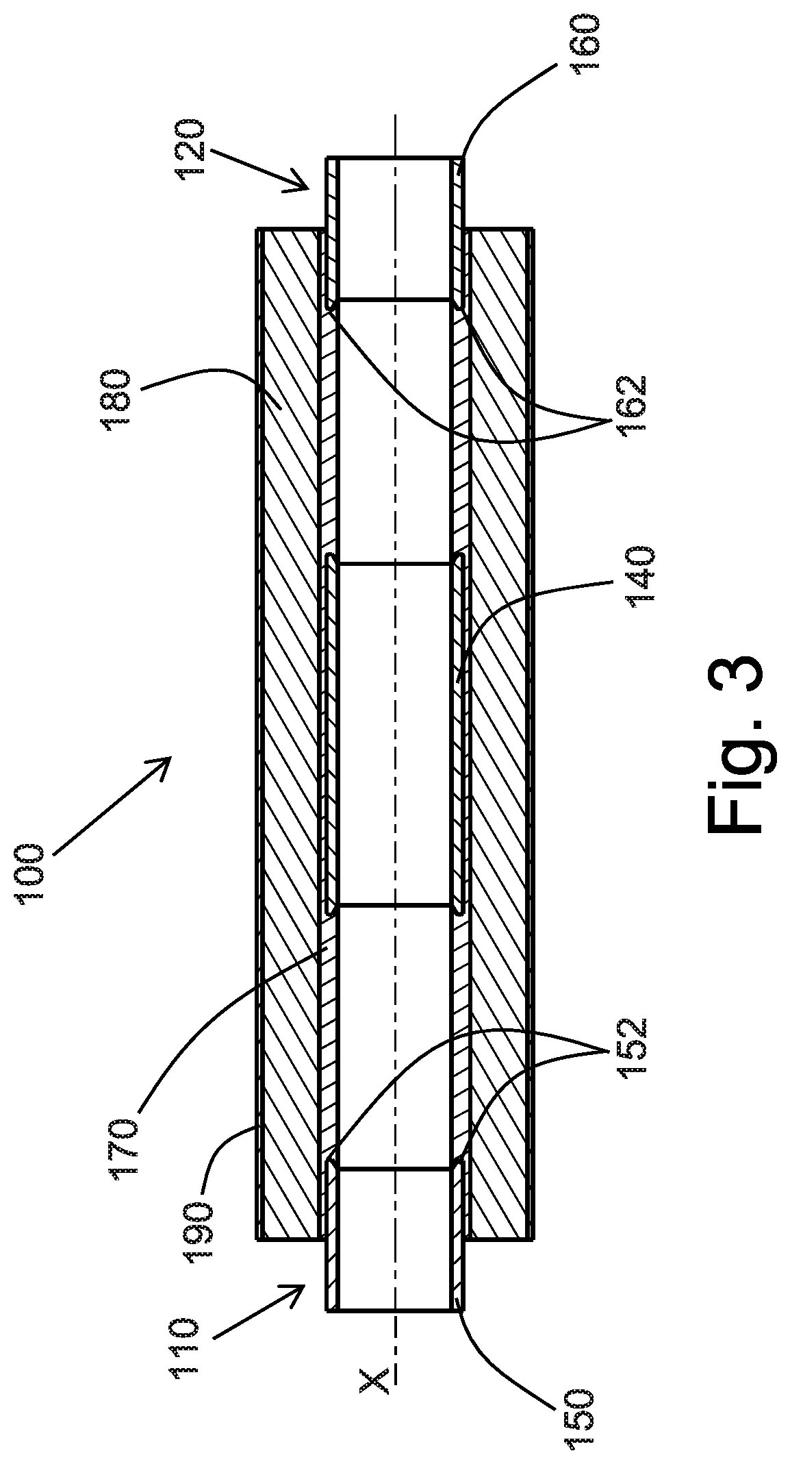
[0049]A joint 100 for the connection of two HVDC cables 200, 300 according to the present invention is shown in FIGS. 1 to 6.

[0050]In particular, FIGS. 1 and 5 show a joint 100 according to the invention assembled on two joined HVDC cables 200, 300 each comprising respective conducting core 20, 30 and a cable insulation system surrounding the respective conducting core 20, 30. Each cable insulation system comprises a cable inner semiconductive layer (not illustrated) surrounding and in contact with the respective conducting core 20, 30, a cable insulating layer 22, 32, surrounding and in contact with the respective inner semiconductive layer, and a cable outer semiconductive layer 24, 34, surrounding and in contact with the respective insulating layer 22, 32. Around to the outer semiconductive layer 24, 34 a metal screen 28, 38 is provided.

[0051]During junction operation, the end portion of each HVDC cable 200, 300 to be connected is peeled so as to expose a tract of conducting core...


PUM

PropertyMeasurementUnit
voltageaaaaaaaaaa
voltageaaaaaaaaaa
conductivityaaaaaaaaaa

Abstract

A joint for high voltage direct current cables extending along a longitudinal axis between two opposite end portions, the joint including: —a central semiconducting electrode; —two semiconducting deflectors; —a field grading layer longitudinally extending between each one of the deflectors and the central electrode and in electric contact therewith; —a joint insulating layer surrounding the central electrode, the two deflectors and the field grading layer; and —a joint outer semiconductive layer surrounding and in direct contact with the insulating layer.

Description

BACKGROUND OF THE INVENTION[0001]The present invention relates to a joint for high voltage direct current (HVDC) cables.[0002]In this specification, the expression “high voltage” (HV) indicates voltages equal or greater than 30 KV. When the voltage is greater than 300 kV, the expression “extra high voltage” (EHV) can be used.[0003]HVDC cables include at least one cable core. The cable core is usually formed by an electrically conductive metal conductor covered by an insulation system. The insulation system is sequentially formed by an inner polymeric layer having semiconductive properties, an intermediate polymeric layer having electrically insulating properties, and an outer polymeric layer having semiconductive properties.[0004]Cable joints are accessories used in an energy network to connect energy cables and to restore the insulation and electric field control over the exposed junction between the conductors of the joined cables.[0005]During assembly operation, the outer semicon...

Claims


Application Information

Patent Timeline
Patent Type & Authority Patents(United States)
IPC IPC(8): H02G15/184
CPCH02G15/184
Inventor BOFFI, PAOLO
Owner PRYSMIAN SPA
Why Eureka
Try Eureka