Polarizing plate with optical compensation layer and organic EL panel using same

a technology of optical compensation layer and organic el panel, which is applied in the direction of polarizing elements, optical elements, instruments, etc., can solve the problems of undesired coloring of hues narrow wavelength bands in which to obtain satisfactory antireflection characteristics, and large reflection in the oblique direction, etc., to achieve excellent antireflection characteristic excellent antireflection characteristi

Active Publication Date: 2021-02-09
NITTO DENKO CORP
View PDF49 Cites 2 Cited by
  • Summary
  • Abstract
  • Description
  • Claims
  • Application Information

AI Technical Summary

Benefits of technology

[0012]According to the present invention, the four optical compensation layers each showing a refractive index characteristic of nx>nz>ny are used in the polarizing plate with optical compensation layers. Accordingly, the polarizing plate with optical compensation layers having the following features can be obtained: the polarizing plate is excellent in antireflection characteristic in an oblique direction while maintaining an excellent antireflection characteristic in a front direction; the polarizing plate can achieve such excellent antireflection characteristics over a wide wavelength band; and the polarizing plate has a neutral hue in the oblique direction.

Problems solved by technology

The organic EL panel has a metal layer having high reflectivity, and hence is liable to cause a problem of, for example, reflection of ambient light or reflection of a background.
However, conventional circularly polarizing plates each involve a problem in that a reflectance in an oblique direction is large (i.e., an antireflection characteristic in the oblique direction is insufficient).
In addition, the conventional circularly polarizing plates each involve a problem in that a wavelength band in which a satisfactory antireflection characteristic is obtained is narrow.
Further, the conventional circularly polarizing plates each involve a problem in that a hue in the oblique direction undergoes undesired coloring.

Method used


Image

  • Polarizing plate with optical compensation layer and organic EL panel using same
  • Polarizing plate with optical compensation layer and organic EL panel using same

Examples


example 1

(i) Production of First Optical Compensation Layer

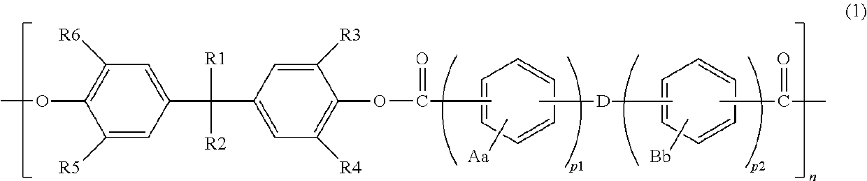
(i-1) Synthesis of Polyarylate

[0096]27.0 kg of 2,2-bis(4-hydroxyphenyl)-4-methylpentane and 0.8 kg of tetrabutylammonium chloride were dissolved in 250 L of a sodium hydroxide solution in a reaction vessel equipped with a stirring apparatus. To the stirred solution, a solution obtained by dissolving 13.5 kg of terephthaloyl chloride and 6.30 kg of isophthaloyl chloride in 300 L of toluene was added all at once, followed by stirring at room temperature for 90 minutes. Thus, a polycondensation solution was obtained. After that, the polycondensation solution was separated by being left to stand still to separate a toluene solution containing polyarylate. Next, the separated liquid was washed with aqueous acetic acid and further washed with ion-exchanged water. After that, the washed product was loaded into methanol to precipitate the polyarylate. The precipitated polyarylate was filtered and dried under reduced pressure to provide 34.1 ...

example 2

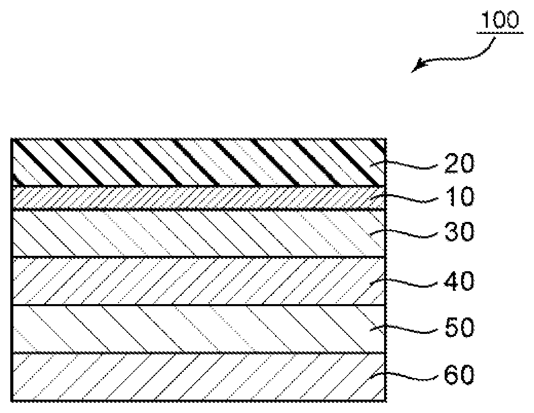
[0108]A polarizing plate with optical compensation layers having the configuration “protective layer / polarizer / first optical compensation layer / second optical compensation layer / third optical compensation layer / fourth optical compensation layer” was obtained in the same manner as in Example 1 except that: the Nz coefficient of the first optical compensation layer was set to 0.75 by changing the stretching conditions at the time of the production of the first optical compensation layer; and the lamination was performed so that the absorption axis of the polarizer and the slow axis of the first optical compensation layer were substantially parallel to each other. Further, an organic EL panel was produced in the same manner as in Example 1 except that the polarizing plate with optical compensation layers was used. The polarizing plate with optical compensation layers and the organic EL panel thus obtained were subjected to the same evaluations as those of Example 1. The results are sho...

example 3

[0109]A polarizing plate with optical compensation layers having the configuration “protective layer / polarizer / first optical compensation layer / second optical compensation layer / third optical compensation layer / fourth optical compensation layer” was obtained in the same manner as in Example 1 except that the lamination was performed so that the angle formed by the absorption axis of the polarizer and the slow axis of the second optical compensation layer became 6°, and the angle formed by the absorption axis of the polarizer and the slow axis of the third optical compensation layer became 33°. Further, an organic EL panel was produced in the same manner as in Example 1 except that the polarizing plate with optical compensation layers was used. The polarizing plate with optical compensation layers and the organic EL panel thus obtained were subjected to the same evaluations as those of Example 1. The results are shown in Table 1.


PUM

PropertyMeasurementUnit
wavelengthaaaaaaaaaa
angleaaaaaaaaaa

Abstract

There is provided a polarizing plate with optical compensation layers having the following features: the polarizing plate is excellent in antireflection characteristic in an oblique direction while maintaining an excellent antireflection characteristic in a front direction; the polarizing plate can achieve such excellent antireflection characteristics over a wide wavelength band; and the polarizing plate has a neutral hue in the oblique direction. A polarizing plate with optical compensation layers according to the present invention is used for an organic EL panel. The polarizing plate with optical compensation layers includes: a polarizer; a first optical compensation layer; a second optical compensation layer; a third optical compensation layer; and a fourth optical compensation layer. Each of the first optical compensation layer, the second optical compensation layer, the third optical compensation layer, and the fourth optical compensation layer shows a refractive index characteristic of nx>nz>ny.

Description

TECHNICAL FIELD[0001]The present invention relates to a polarizing plate with optical compensation layers and an organic EL panel using the same.BACKGROUND ART[0002]In recent years, along with widespread use of thin displays, a display having an organic EL panel mounted thereon (organic EL display apparatus) has been proposed. The organic EL panel has a metal layer having high reflectivity, and hence is liable to cause a problem of, for example, reflection of ambient light or reflection of a background. In view of the foregoing, it has been known that such problem is prevented by arranging a circularly polarizing plate on a viewer side. A circularly polarizing plate in which a retardation film (typically a λ / 4 plate) is laminated so that its slow axis may form an angle of about 45° with regard to the absorption axis of a polarizer has been known as a general circularly polarizing plate. In addition, an attempt has been made to laminate retardation films (optical compensation layers)...

Claims


Application Information

Patent Timeline
Patent Type & Authority Patents(United States)
IPC IPC(8): G02B5/30B32B7/02G02B1/14H01L51/52B32B7/023
CPCG02B5/3041B32B7/02G02B1/14G02B5/3083H01L51/5262H01L51/5281G02B5/3033G02B1/111B32B7/023G02B5/305H10K50/86H10K50/85
Inventor IIDA, TOSHIYUKIYAGINUMA, HIRONORI
Owner NITTO DENKO CORP
Why Eureka
Try Eureka