

Data cable for areas at risk of explosion
- Summary
- Abstract
- Description
- Claims
- Application Information
AI Technical Summary
Benefits of technology
Problems solved by technology
Method used
Image

Examples
Embodiment Construction
[0034]In the following, without being restricted to these, specific details are set out to provide a complete understanding of the present disclosure. However, it is clear to a person skilled in the art that the present disclosure can be used in other exemplary embodiments that may differ from the details set out below. For example, specific configurations and arrangements of a data cable are described below that should not be regarded as restrictive. Furthermore, various application fields of the data cable are conceivable.
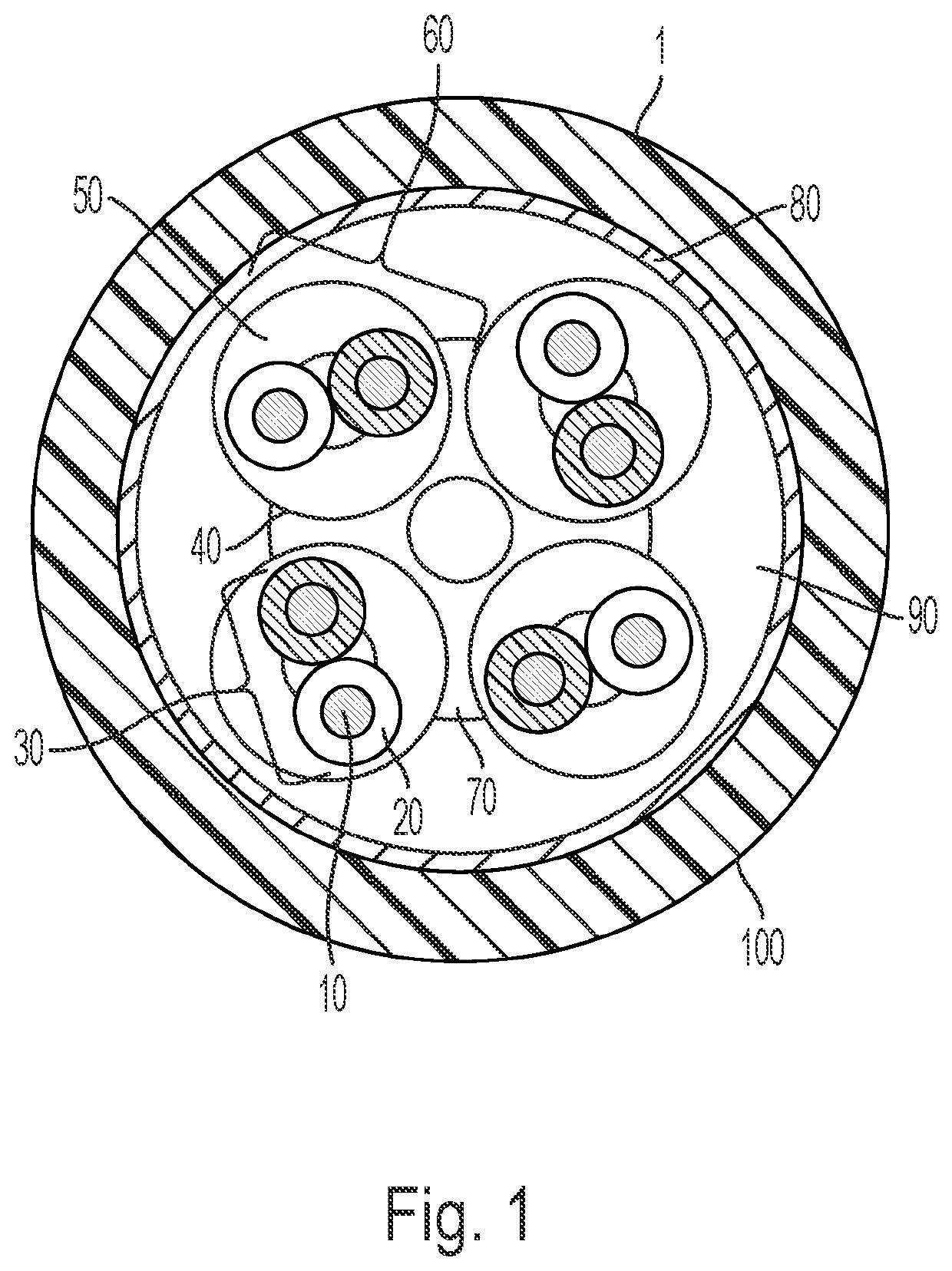
[0035]FIG. 1 shows a data cable 1. The data cable 1 in FIG. 1 has, purely as an example and without being limited to the number shown, four wire pairs 30 as an example of at least one pair of wires 30 present in the data cable. Each of the four wire pairs 30 has two wires 10 stranded with one another in the longitudinal direction of the data cable. A wire 10 is formed from a conductor (pure metal), which is surrounded by a dielectric (insulation). Together with t...
PUM
 Abstract
Description
Claims
Application Information