Temporary interatrial shunts

a technology of interatrial shunt and shunt, which is applied in the field of medical devices, can solve the problems of cardiac arrhythmias, inability to use the transseptal approach for future interventions, and dislocation of the interatrial septum

Active Publication Date: 2021-03-09
WAVE LTD V +1
View PDF498 Cites 17 Cited by
  • Summary
  • Abstract
  • Description
  • Claims
  • Application Information

AI Technical Summary

Benefits of technology

[0011]Embodiments of the present invention therefore provide—as an alternative to an implanted shunt—shunting apparatus that may be placed within the subject for only a short period of time, e.g., for less than one week, or even less than one day (e.g., 2-3 hours, 3-6 hours, or 6-12 hours). The apparatus comprises a shunt, along with one or more wires that extend from the proximal portion of the shunt to the exterior of the subject. These wires, which are typically controlled via a control handle, may be used to collapse the shunt, whenever the shunt is no longer needed. Following the collapse of the shunt, the shunt may be easily withdrawn from the subject.
[0012]In some embodiments, another wire, which passes circumferentially along the intermediate portion of the shunt and also extends to the exterior of the subject, may be used to adjust the diameter of the shunt while the shunt is inside the subject, thus regulating the flow of blood across the interatrial septum.

Problems solved by technology

An implanted interatrial shunt may cause various complications, such as distortion of the interatrial septum, cardiac arrhythmias, inability to use the transseptal approach for future interventions, paradoxical embolism, and / or blood desaturation.
Hence, for cases in which an interatrial shunt is required only temporarily (i.e., for a short period of time, such as less than one week), an implanted shunt may not necessarily be the most appropriate solution for treatment.

Method used


Image

  • Temporary interatrial shunts
  • Temporary interatrial shunts
  • Temporary interatrial shunts

Examples


Embodiment Construction

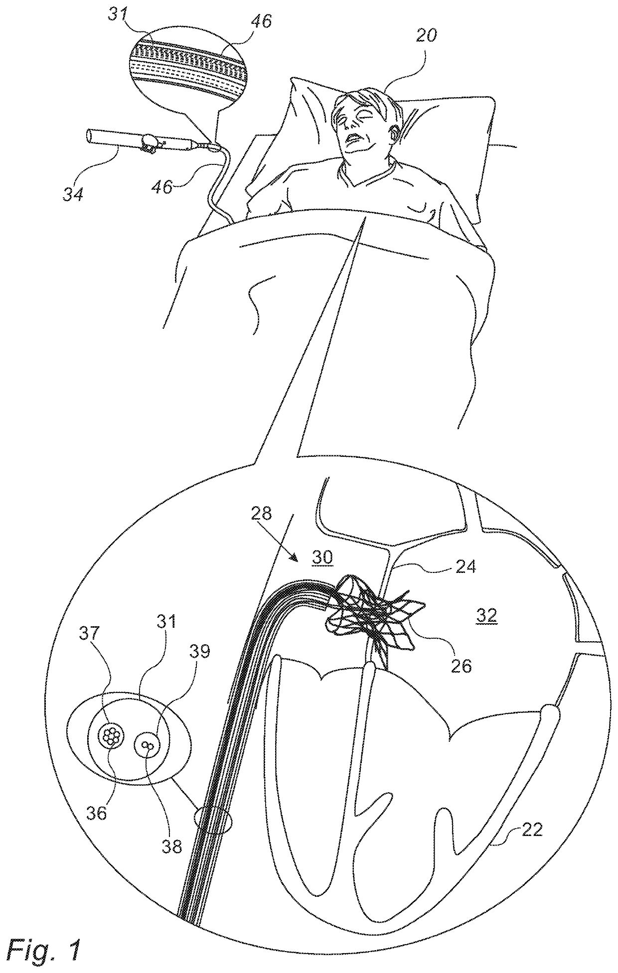
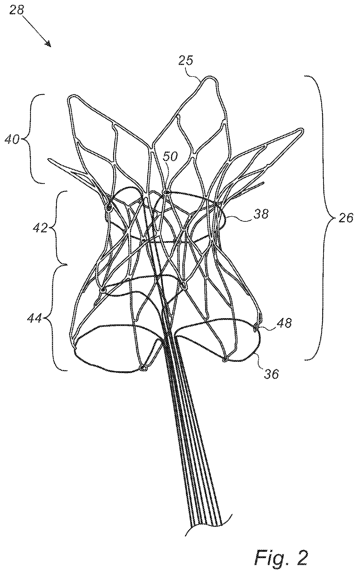
[0049]Reference is initially made to FIG. 1, which is a schematic illustration of a temporary shunt apparatus 28 inside a subject 20, and to FIG. 2, which is a schematic illustration of temporary shunt apparatus 28, in accordance with some embodiments of the present invention.

[0050]Apparatus 28 comprises a shunt 26, which may be placed between two chambers of the heart 22 of subject 20, such as within the interatrial septum 24 of heart 22, between the right atrium 30 and the left atrium 32. Alternatively, the shunt may be placed between the two ventricles of the heart, or between any other two body cavities. Shunt 26 typically comprises a flared distal portion 40, a flared proximal portion 44, and an intermediate portion 42, which is disposed between distal portion 40 and proximal portion 44. Distal portion 40 and proximal portion 44 anchor the shunt to septum 24 (i.e., prevent migration of the shunt from within the septum), while intermediate portion 42 provides a passageway across...


PUM


Abstract

Described embodiments include apparatus (28) that includes a shunt (26). The shunt includes a flared distal portion (40), a flared proximal portion (44), and an intermediate portion (42), disposed between the distal portion and the proximal portion. The apparatus further includes a constricting flexible longitudinal element (38) passing circumferentially along the intermediate portion of the shunt, configured to constrict the intermediate portion of the shunt, and one or more proximal-portion-collapsing flexible longitudinal elements (36) configured to collapse the proximal portion of the shunt. Other embodiments are also described.

Description

CROSS-REFERENCE TO RELATED APPLICATIONS[0001]The present application claims priority from U.S. Provisional Application 62 / 158,022, entitled “Percutaneous device for temporary stenting and shunting,” filed May 7, 2015, whose disclosure is incorporated herein by reference.FIELD OF THE INVENTION[0002]Embodiments of the present invention relate generally to the field of medical devices, and specifically to percutaneous devices for treatment of a subject.BACKGROUND[0003]Some medical conditions are treated by implanting a shunt between two body cavities, typically to release excess pressure from one of the cavities into the other. For example, a shunt may be implanted between the right and left atria of the heart for the treatment of pulmonary hypertension by decompression of the right atrium, or for the treatment of congestive heart failure by decompression of the left atrium. Implantable shunts of this sort are described, for example, in U.S. Pat. No. 8,091,556, whose disclosure is inco...

Claims


Application Information

Patent Timeline
Patent Type & Authority Patents(United States)
IPC IPC(8): A61M27/00A61B17/11A61B17/00A61F2/95A61M25/09
CPCA61M27/002A61B17/11A61B2017/00243A61B2017/1107A61B2017/1139A61F2002/9511A61F2250/0059A61M25/09A61M2205/3344A61M2210/125
Inventor KEREN, GAD
Owner WAVE LTD V
Why Eureka
Try Eureka