Waveform design for locating system

a waveform and positioning system technology, applied in the field of waveforms, can solve problems such as multipath, high signal bandwidth, and inability to easily achieve, and achieve the effects of minimizing interference and similar impairment, and reducing interference between different tag devices and/or known position devices

Active Publication Date: 2021-03-09
FRAUNHOFER GESELLSCHAFT ZUR FOERDERUNG DER ANGEWANDTEN FORSCHUNG EV
View PDF24 Cites 0 Cited by
  • Summary
  • Abstract
  • Description
  • Claims
  • Application Information

AI Technical Summary

Benefits of technology

[0032]With the invention, bandwidth requirements are more relaxed, at least on the receiving device. When multiple tags transmit frequency-hopping signals, less interference between signals is implied. Different pairs (tag device / known position device) can use different hopping patterns to allow for concurrent measurements at the localization device.
[0067]It is also possible, for each tag device and / or known position device, to hop frequency according to a particular fashion, e.g., using a predefined sequence, a predetermined sequence, a random sequence, pseudorandom sequence, or a sequence adapted to an external command. The sequence may follow a particular algorithm, which can also be based on data relating to the devices (e.g., a serial number of the device) which are not (or not easily) repeated throughout the group of devices. In some embodiments, the hopping sequence may be derived from an ID of closest known position device. Hence, it may be guaranteed that the group of devices hop frequency so as to minimize interferences and similar impairments.

Problems solved by technology

However, this is not easily possible for several reasons, e.g., for high bandwidth requirements.
For example, several elements could need to transmit data at the same time, hence increasing the likelihood of interferences between signals, near-far problems, multipath, etc.
However, these systems need high signal bandwidth, needed for sufficient temporal resolution of the burst.
Measurements are in general impaired by errors.
A phase error may propagate as a position error.
In general terms, some incorrect phase measurements are due to an unknown clock bias of a transmitting device.
Other phase errors are due to the clock of one of the receivers. other phase errors are implied by multipath and obstacles.
Hence, reliability of measurements is not optimal.
Further, reliability is not optimal also for other reasons.
High differences in RSS (Received Signal Strength) between reference transmitter and tag (near-far effect) can cause a bad determination of the positions: the signal transmitted by a closer device can hide the signal transmitted by the more distant device.
Further, the periodic transmission from one or multiple reference transmitters may occupy considerable parts of the radio resource.
High energy consumption is often needed to provide accurate localization.
In some cases, this contradicts the idea of IoT devices, which need to be running on a single battery for multiple years.

Method used


Image

  • Waveform design for locating system
  • Waveform design for locating system
  • Waveform design for locating system

Examples


Embodiment Construction

[0111]Hereinafter, embodiments and parts of the invention are discussed.

5.1. The Network of FIG. 1

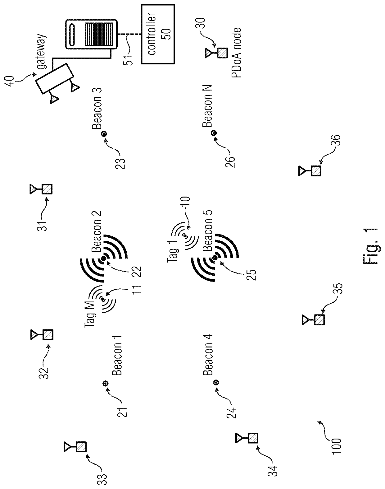
[0112]FIG. 1 shows a system 100 for the localization of at least one tag device (here, “Tag 1”, referred to with 10, and “Tag M”, referred to with 11). The system 100 can comprise the tag devices 10 and 11, whose position is to be determined. The system 100 can also comprise known position devices (here “Beacon 1-N”, being referred to with 21-26), whose position is known. The system 100 can also comprise a localization device configured to localize the tag devices 10 and 11. The localization device (which is in this case a distributed device with several distinct units displaced in different places) can comprise a plurality of (e.g., at least three) receivers 30-36 (which can be PDoA receivers) which permit to calculate the position of the tag devices 10 and 11 by analysing the phase information of signals transmitted by devices 10 and 11 and known position devices 21-26.

[0113]According...


PUM


Abstract

The invention relates to systems and methods for obtaining phase information and / or localization of tag devices. In particular, the invention relates to a system for the localization of at least one tag device, the system including: the at least one tag device configured to transmit a tag signal which is a frequency-hopping signal; at least one known position device configured to transmit a reference signal; and a localization device configured to localize the at least one tag device based on the phase difference of arrival, PDoA, of the tag signal and the reference signal.

Description

CROSS-REFERENCE TO RELATED APPLICATIONS[0001]This application is a continuation of copending International Application No. PCT / EP2016 / 061780, filed May 25, 2016, which is incorporated herein by reference in its entirety.1. TECHNICAL FIELD[0002]Embodiments according to the invention create system and methods for the localization of at least one tag device and / or for the acquiring phase differences between wireless signals.[0003]In particular, embodiments of the invention refer to a reference transmitter selection and waveform design for a locating system.2. BACKGROUND OF THE INVENTION[0004]Accurate localization (e.g., for the Internet-of-Things, IoT) is needed for many use cases, e.g. asset tracking, in particular in indoor environments.[0005]However, this is not easily possible for several reasons, e.g., for high bandwidth requirements. For example, several elements could need to transmit data at the same time, hence increasing the likelihood of interferences between signals, near-f...

Claims


Application Information

Patent Timeline
Patent Type & Authority Patents(United States)
IPC IPC(8): G01S5/06G01S5/02G01S13/74G01S13/87G01S5/14
CPCG01S5/06G01S5/0226G01S5/14G01S13/74G01S13/878
Inventor SACKENREUTER, BENJAMINHADASCHIK, NIELSTHIELECKE, JOERN
Owner FRAUNHOFER GESELLSCHAFT ZUR FOERDERUNG DER ANGEWANDTEN FORSCHUNG EV
Why Eureka
Try Eureka