Non-personal basic service point / access point (PCP/AP) communication device, non-PCP/AP communication method, PCP/AP communication device and PCP/AP communication method

a communication device and non-personal technology, applied in the field of non-personal basic service point/access point (pcp/ap) communication devices, can solve the problems of difficult wireless connection for wireless terminals, achieve the effect of reducing the occurrence of unnecessary interference waves as to other stas, avoiding unnecessary ssw frames, and reducing the electric power consumption of communication devices

Active Publication Date: 2021-03-09
PANASONIC INTELLECTUAL PROPERTY CORP OF AMERICA
View PDF15 Cites 0 Cited by
  • Summary
  • Abstract
  • Description
  • Claims
  • Application Information

AI Technical Summary

Benefits of technology

[0004]In communication device according to an aspect of the present disclosure, a wireless device (STA) can determine whether or not an SSW frame in A-BFT will reach a communication device (AP) or not, thereby contributing to providing of a communication device and communication method where unnecessary transmission of SSW frames can be avoided, so electric power consumption of the communication device (STA) can be reduced, and occurrence of unnecessary interference waves as to other STAs can be reduced.
[0006]According to a communication device and communication method of an aspect of the present disclosure, a wireless device (STA) can determine whether or not an SSW frame in A-BFT will reach a communication device (AP) or not, and unnecessary transmission of SSW frames can be avoided, so electric power consumption of the communication device (STA) can be reduced, and occurrence of unnecessary interference waves as to other STAs can be reduced.

Problems solved by technology

However, communication areas of wireless terminals are not taken into consideration, there are cases where, even if a first wireless terminal can receive a frame used for training for beamforming from a second wireless terminal, it is difficult for the second wireless terminal receive a frame used for training for beamforming from the first wireless terminal, and it is difficult for the wireless terminals to establish a wireless link.

Method used


Image

  • Non-personal basic service point / access point (PCP/AP) communication device, non-PCP/AP communication method, PCP/AP communication device and PCP/AP communication method
  • Non-personal basic service point / access point (PCP/AP) communication device, non-PCP/AP communication method, PCP/AP communication device and PCP/AP communication method
  • Non-personal basic service point / access point (PCP/AP) communication device, non-PCP/AP communication method, PCP/AP communication device and PCP/AP communication method

Examples


first embodiment

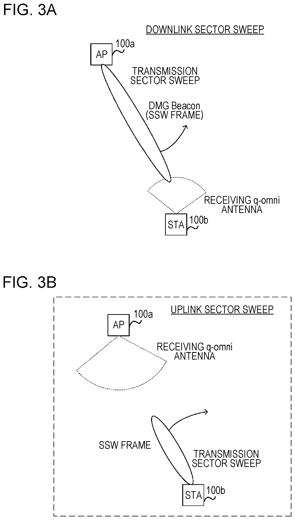
[0087]In a first embodiment, description will be made regarding a method of the communication device (STA) 100b determining whether or not the communication device (AP) 100a can receive an SSW frame in an uplink sweep, using DMG Beacon reception power, and reception gain of the quasi-omnidirectionality (quasi-omni) antenna of the communication device (AP) 100a used at the time of the uplink sector sweep included in the DMG Beacon in a downlink sector sweep.

[0088]FIG. 4 is a diagram illustrating an example of the configuration of a communication device 100 according to the present disclosure. The communication device 100 includes a MAC control unit 101, a PHY transmission circuit 102, a D / A converter 103, a transmission RF circuit 104, a transmitting q-omni antenna 105, the transmitting array antenna 106, a PHY reception circuit 112, an A / D converter 113, a reception RF circuit 114, the receiving q-omni antenna 115, and the receiving array antenna 116.

[0089]The MAC control unit 101 g...

second embodiment

Modification of Second Embodiment

[0193]Although the value of the TX EIRP and the value of the A-BFT RX Antenna Gain are each transmitted in a DMG Beacon frame in the second embodiment, a difference between the value of the TX EIRP field and the value of the A-BFT RX Antenna Gain is transmitted in a modification of the second embodiment.

[0194]FIG. 18 illustrates a different example of the format of the DMG Beacon frame. The DMG Beacon frame in FIG. 18 includes the SSW field in the Frame Body, and includes the Differential Gain field in the SSW field.

[0195]FIG. 19 illustrates an example of the value of the Differential Gain field. The value of Differential Gain (DIFF_Gain_Beacon) represents the difference between the value of the TX EIRP and the value of the A-BFT RX Antenna Gain, and is calculated by Expression 5.

DIFF_Gain_Beacon=EIRP_Beacon−RxGain_ABFT  (Expression 5)

[0196]The AP1 decides the value of the Differential Gain field in accordance with the accuracy of the value of Differ...

third embodiment

[0222]Although the communication device (STA) 100b determines whether or not to transmit an SSW frame based on a DMG Beacon frame received from one communication device (AP) 100a in the first embodiment and second embodiment, the communication device (STA) 100b determines whether or not to transmit an SSW frame based on a DMG Beacon frame received from multiple communication devices (AP) 100a in a third embodiment.

[0223]FIG. 22 is a diagram illustrating an example of procedures for communication between the communication device (AP) 100a (hereinafter, AP1) and communication device (STA) 100b (hereinafter, STA1).

[0224]In step S301, the AP1 transmits a DMG Beacon frame with a Neighbor Report element included therein. Note that the STA1 has already completed association with the AP1 before step S301.

[0225]FIG. 23 illustrates an example of the format of a DMG Beacon frame. The Neighbor Report element includes information of APs present nearby the AP1 (e.g., AP2), that the AP1 has detect...


PUM


Abstract

A non-personal basic service point / access point (PCP / AP) communication device includes a reception circuit that receives a DMG Beacon frame, a judging circuit that judges whether or not to transmit a frame used for beamforming training (BFT), using information relating to reception antenna gain of a PCP / AP communication device included in a DMG Beacon frame and information relating to reception power of a DMG Beacon frame, and a transmission circuit that transmits the frame used for BFT in a case of the judging circuit having judged to transmit the frame used for BFT.

Description

BACKGROUND1. Technical Field[0001]The present disclosure relates to a non-personal basic service point / access point (PCP / AP) communication device, a non-PCP / AP communication method, a PCP / AP communication device and a PCP / AP communication method.2. Description of the Related Art[0002]IEEE 802.11 is one of wireless LAN related standards, one of which is, for example, the IEEE 802.11ad (hereinafter referred to as “11ad standard”) (e.g., see IEEE 802.11ad™—2012 pp 278-314). Beamforming (BF) technology is used in the 11ad standard. Beamforming is a method where communication is performed by changing the directionality of one or more antennas of a transmission unit and reception unit included in a wireless terminal, to set antenna directionality so that communication quality, such as reception strength for example, is optimal.SUMMARY[0003]However, communication areas of wireless terminals are not taken into consideration, there are cases where, even if a first wireless terminal can recei...

Claims


Application Information

Patent Timeline
Patent Type & Authority Patents(United States)
IPC IPC(8): H04B7/06H04W40/24H04W80/02H04W72/04H04W16/28H04B7/0456H04B7/08H04W84/12
CPCH04B7/0695H04B7/0469H04B7/06H04B7/0617H04B7/0623H04B7/088H04W16/28H04W40/244H04W72/046H04W72/0446H04W80/02H04W84/12Y02D30/70H04B7/0417
Inventor WEE, YAO HUANG GAIUSMOTOZUKA, HIROYUKIHUANG, LEIURUSHIHARA, TOMOYAIRIE, MASATAKA
Owner PANASONIC INTELLECTUAL PROPERTY CORP OF AMERICA
Why Eureka
Try Eureka