Razor assembly with spring-biased connecting head

a technology of connecting head and razor, which is applied in the direction of metal working apparatus, etc., can solve the problems of improper provision of pivoting movement or complex structure of razor, and achieve the effect of avoiding the need for a pivoting movement or a complex structure of the razor

Active Publication Date: 2021-03-30
DORCO CO LTD
View PDF33 Cites 5 Cited by
  • Summary
  • Abstract
  • Description
  • Claims
  • Application Information

AI Technical Summary

Benefits of technology

[0009]Aspects of the present disclosure also provide a razor assembly that provides the pivoting movement about the rotation axis with a simpler structure and is not deformed even after being used for a long period of time.

Problems solved by technology

However, a case in which a structure of a razor becomes complicated to provide various movements of such a multiaxial pivoting razor or a pivoting movement is not properly provided due to a structural weakness may occur.

Method used


Image

  • Razor assembly with spring-biased connecting head
  • Razor assembly with spring-biased connecting head
  • Razor assembly with spring-biased connecting head

Examples


first embodiment

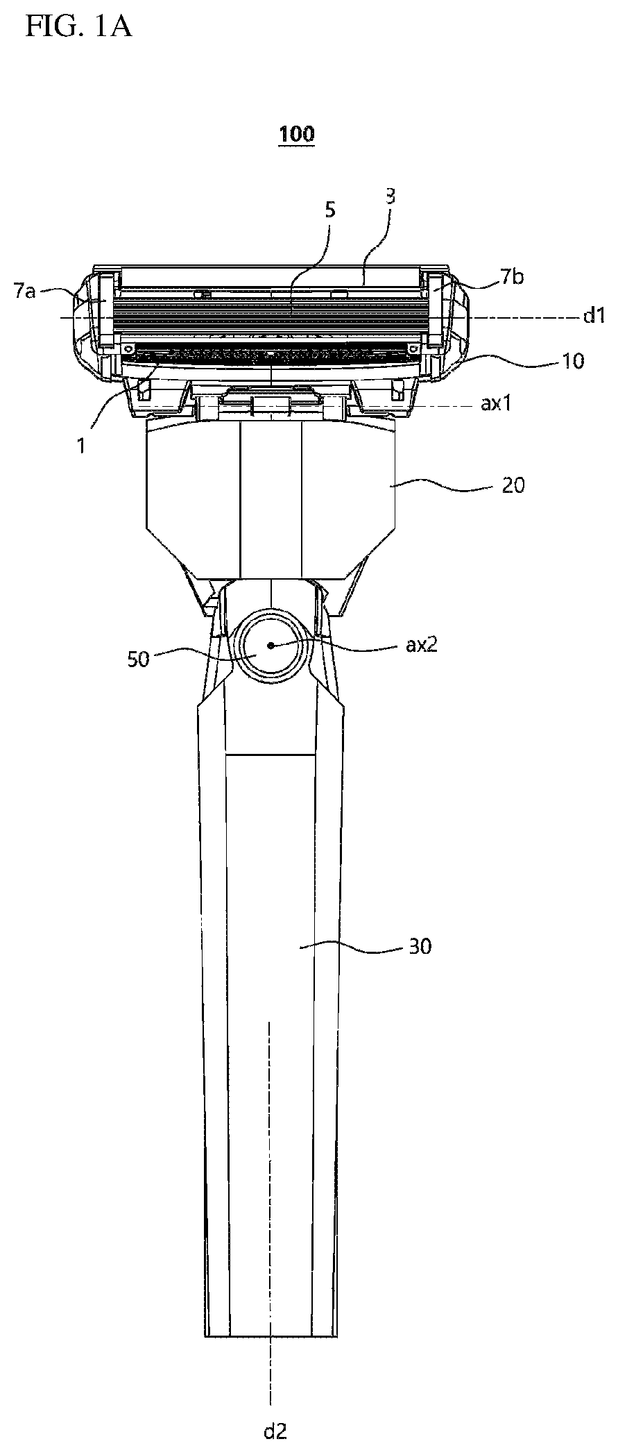
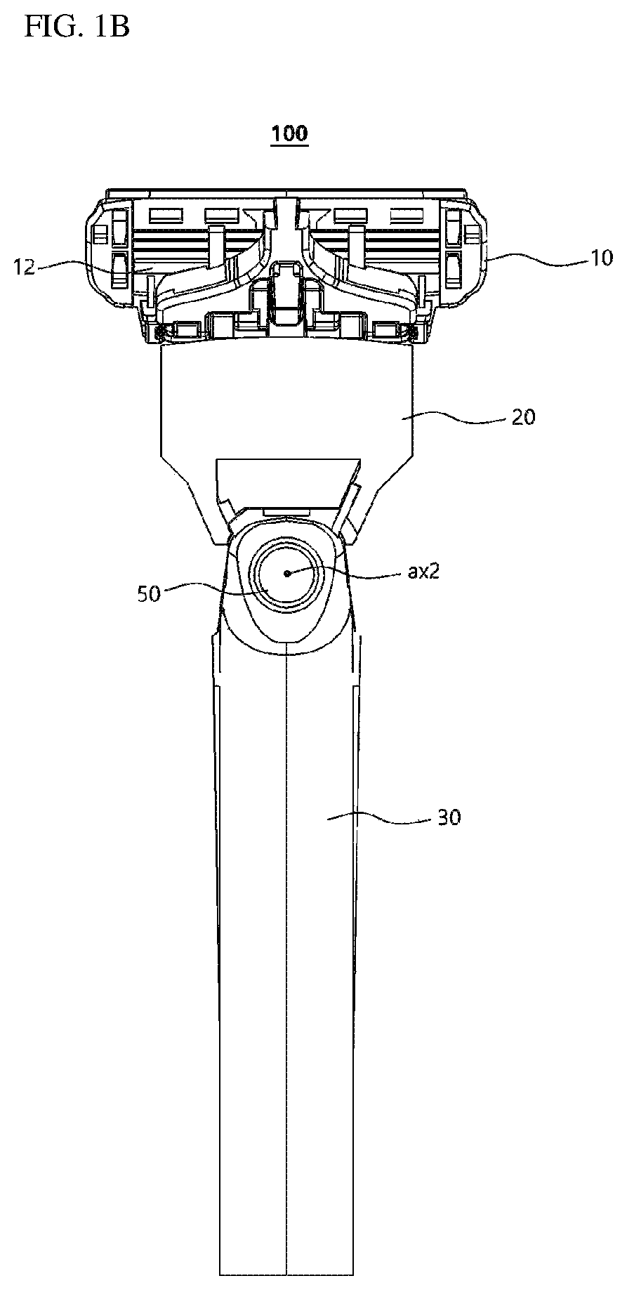
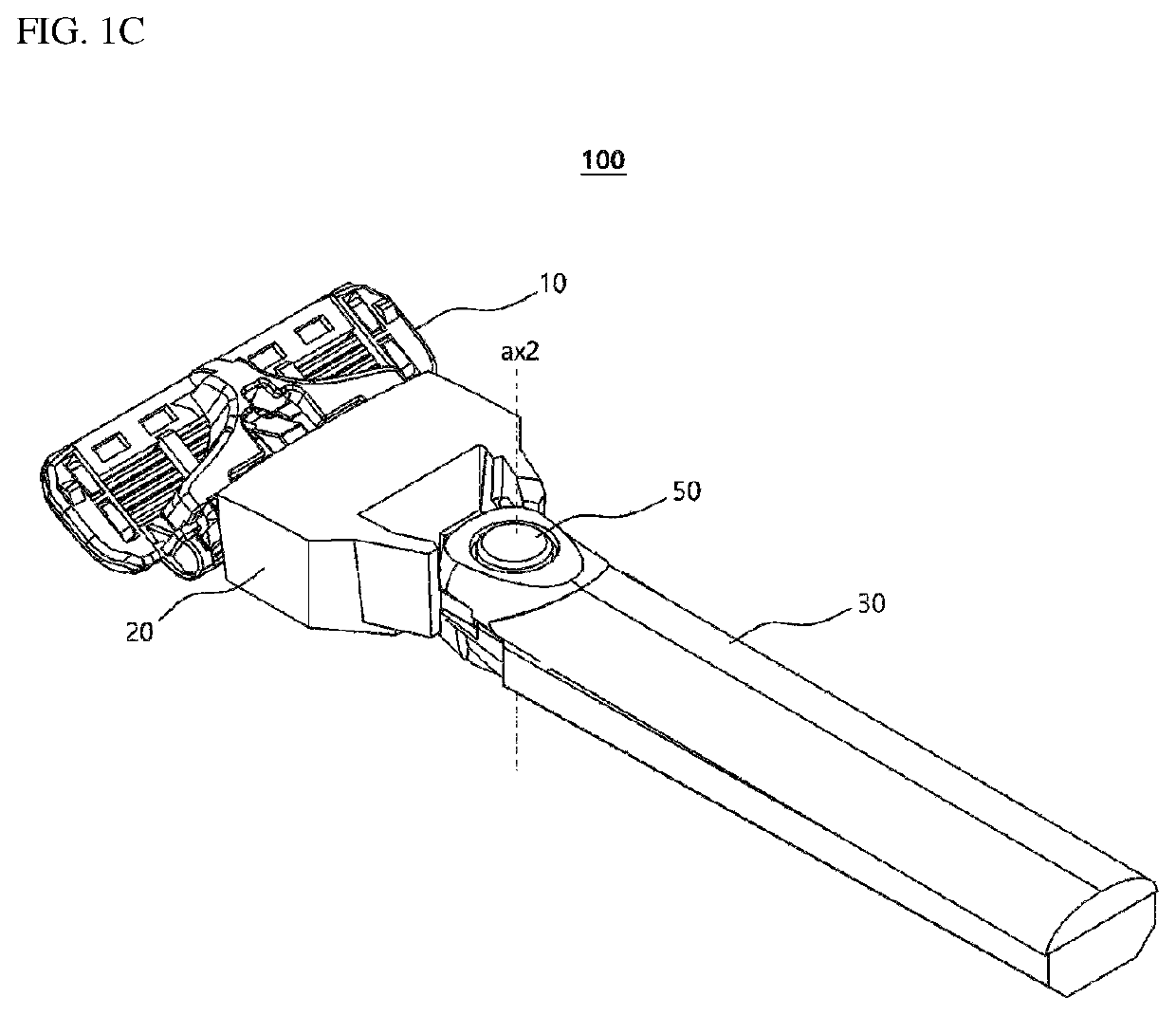
[0035]FIG. 1A is a plan view of a razor assembly 100 according to the present disclosure that is seen from the front of a razor handle 30 (from a side at which a front surface of a blade housing 10 is visible), FIG. 1B is a rear view thereof seen from the rear of the razor handle 30, and FIG. 1C is a perspective view thereof seen from one side of the rear of the razor handle 30.

[0036]The razor assembly 100 according to the first embodiment of the present disclosure may include a razor cartridge including a razor blade 5 and the blade housing 10, a connecting head 20, and the razor handle 30. One end of the razor blade 5 includes a cutting edge, and the other end thereof is seated on a seating portion included in the blade housing 10. In this case, a single razor blade 5 or two or more razor blades 5 may be disposed, and a direction in which the razor blade 5 is accommodated in the blade housing 10 is a transverse direction d1 that is perpendicular to a shaving direction.

[0037]In ord...

second embodiment

[0057]FIG. 6A is a plan view of the razor assembly 200 according to the present disclosure that is seen from the front of the blade housing 10, FIG. 6B is a rear view thereof seen from the rear of the blade housing 10, and FIG. 6C is a perspective view thereof seen from one side of the rear of the blade housing 10.

[0058]The razor assembly 200 according to the second embodiment of the present disclosure may include a razor cartridge including the razor blade 5 and the blade housing 10, a connecting head 120, and a razor handle 130. One end of the razor blade 5 includes a cutting edge, and the other end thereof is seated on a seating portion included in the blade housing 10. In this case, a single razor blade 5 or two or more razor blades 5 may be disposed, and a direction in which the razor blade 5 is accommodated in the blade housing 10 is a transverse direction d1 that is perpendicular to a shaving direction.

[0059]In FIG. 6A, the connecting head 120 is detachably coupled to the bla...

third embodiment

[0072]FIG. 10 is a perspective view of the razor assembly 300 according to the present disclosure that is seen from the rear.

[0073]The razor assembly 300 according to the third embodiment of the present disclosure may include the blade housing 10, the connecting head 220, and a razor handle 230. The connecting head 220 is detachably coupled to the blade housing 10 at the rear surface of the blade housing 10. In this case, the blade housing 10 may pivot about the first axis ax1, which is parallel to the transverse direction d1 in which the razor blade is accommodated, with respect to an end of the connecting head.

[0074]Meanwhile, the connecting head 220 is also coupled with the razor handle 230 so that the connecting head 220 is pivotable about the rotation axis ax2, which is perpendicular to the transverse direction d1. The rotation axis, i.e., the second axis ax2, is formed in a direction that is perpendicular to both the transverse direction d1 and the longitudinal direction d2 of...


PUM


Abstract

A razor assembly includes at least one razor blade having a cutting edge, a blade housing configured to accommodate the at least one razor blade aligned along first direction, a connecting head configured to be detachably coupled to the blade housing, a razor handle configured to support the connecting head so that the connecting head is pivotable about a rotation axis, which is perpendicular to the first direction, and a torsion spring configured to be elastically deformed when the connecting head pivots about the rotation axis from a neutral position so that the torsion spring provides a restoring force for the connecting head to return to the neutral position.

Description

[0001]Pursuant to 35 U.S.C. § 119(a), this application claims the benefit of earlier filing date and right of priority to Korean Patent Application No. 10-2017-0155830, filed on Nov. 21, 2017, the contents of which are all hereby incorporated by reference herein in its entirety.BACKGROUND1. Field of the Disclosure[0002]The present disclosure relates to a razor assembly, and more particularly, to a razor assembly which is pivotable about a rotation axis which is perpendicular to a direction in which razor blades are aligned.2. Description of the Related Art[0003]Generally, a conventional razor assembly, which is known as a wet razor, includes a razor cartridge and a razor handle. Generally, the razor cartridge includes at least one blade disposed between a rear side of a guard bar and a front side of a cap. The razor cartridge is installed to be pivotable on the razor handle so that the razor cartridge is able to pivot, with respect to the razor handle, between a neutral position and...

Claims


Application Information

Patent Timeline
Patent Type & Authority Patents(United States)
IPC IPC(8): B26B21/52B26B21/22B26B21/40
CPCB26B21/521B26B21/225B26B21/4012
Inventor KIM, DONGIL
Owner DORCO CO LTD
Why Eureka
Try Eureka