Distributed energy storage system

a technology of distributed energy and storage system, which is applied in the direction of power installations, transportation and packaging, sustainable transportation, etc., can solve the problems of increasing drag, reducing the efficiency of the aircraft during flight, and increasing drag

Active Publication Date: 2021-03-30
CRACKER JACK LLC
View PDF7 Cites 2 Cited by
  • Summary
  • Abstract
  • Description
  • Claims
  • Application Information

AI Technical Summary

Benefits of technology

[0015]By providing a modular system whereby the mass distribution of energy storage units can be adjusted, for example along the length of an aircraft, changes in the CG due to loading of the aircraft can be compensated. The overall CG of the aircraft can therefore be tuned to remain within a relatively small envelope for a variety of loading conditions, allowing smaller tail volume coefficients to be used.

Problems solved by technology

One result of this is that the length of the moment arm available to the horizontal stabilizer is reduced, and the area of stabilizer must therefore be increased to provide the same counteracting effect, increasing drag and reducing the efficiency of the aircraft during flight.
In order to maintain a high Vh the horizontal tail area Sh of these aircraft must be further increased, causing greater drag and reducing their efficiency still further.

Method used


Image

  • Distributed energy storage system
  • Distributed energy storage system
  • Distributed energy storage system

Examples


Embodiment Construction

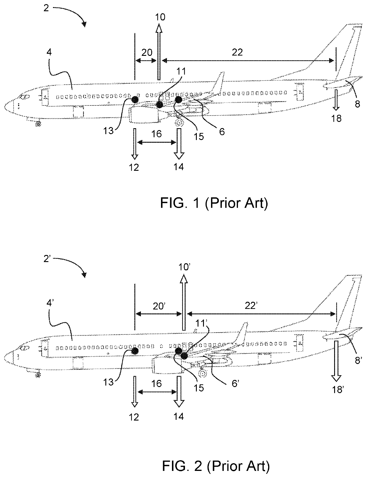
[0030]FIG. 1 shows a side view of a loaded passenger aircraft 2. The aircraft briefly comprises a fuselage 4, a wing 6 and a horizontal stabiliser or tail 8. Lift 10 is generated predominantly by the wing 6, and can be considered to act at a longitudinal position 11 towards the leading edge of the wing 6. The position of this centre of lift 11 can be assumed to be fixed.

[0031]The lift 10 is required to overcome the aircraft weight 12 and payload weight 14 which are indicated separately in FIG. 1. The centre of gravity (CG), for the unloaded aircraft will be fixed, so the aircraft CG 13, through which the aircraft weight 12 acts, will not move.

[0032]The longitudinal distance between the centre of lift 11 and the aircraft CG 13 is known as the static margin. In the illustrated example, the aircraft CG 13 is ahead of the centre of lift 11, so the aircraft 2 is said to have a positive static margin.

[0033]The CG for the payload may vary depending on how the aircraft is loaded, but its lo...


PUM


Abstract

A modular energy storage system within a vehicle, wherein the energy storage system comprises a plurality of discrete energy storage units which are movable within the vehicle and selectively securable in a variety of positions.

Description

CROSS-REFERENCE TO RELATED APPLICATIONS[0001]This application is based upon and claims the benefit of priority from British Patent Application No. GB 1811982.6, filed on 23 Jul. 2018, the entire contents of which are incorporated by reference.BACKGROUNDTechnical Field[0002]The present disclosure relates to a distributed energy storage system. More particularly, the present disclosure relates to a distributed energy storage system in an aircraft.Description of the Related Art[0003]Conventional aircraft consist of a fuselage, to be filled with payload, supported by a wing. Most fuselage designs are substantially in the form of a tube and generate only a small amount of lift. The majority of lift is produced by the wing, with the result that an aircraft's centre of lift or centre of pressure will typically be located at a longitudinal position, usually approximated at 25%, along the mean aerodynamic chord of the wing aerofoil.[0004]For reasons of stability, an aircraft's centre of grav...

Claims


Application Information

Patent Timeline
Patent Type & Authority Patents(United States)
IPC IPC(8): B64D27/24
CPCB64D27/24B64D2221/00B64C17/00B64C17/10Y02T50/40Y02T50/60B64D27/02B64D2041/005
Inventor MOXON, MATTHEW
Owner CRACKER JACK LLC
Why Eureka
Try Eureka