Turbocharger

a technology of turbocharger and lubricant oil, which is applied in the direction of shafts, bearing components, shafts, etc., can solve the problems of degrading oil substances adhesion and accumulation, reducing the performance of the internal combustion engine, etc., and achieves the effect of compact and simple configuration, and promotion of lubricant oil discharg

Active Publication Date: 2021-03-30
MITSUBISHI HEAVY IND ENGINE & TURBOCHARGER LTD
View PDF26 Cites 2 Cited by
  • Summary
  • Abstract
  • Description
  • Claims
  • Application Information

AI Technical Summary

Benefits of technology

[0041]According to at least one embodiment of the present invention, it is possible to provide a turbocharger whereby it is possible to promote discharge of lubricant oil from a bearing housing through a compact and simple configuration.

Problems solved by technology

If lubricant oil leaks to the compressor housing side housing the compressor in particular, the lubricant oil enters the combustion chamber of the internal combustion engine with intake air, which may produce white smoke or cause degraded oil substances to adhere and accumulate, causing a decrease in the performance of the internal combustion engine.

Method used


Image

  • Turbocharger
  • Turbocharger
  • Turbocharger

Examples


first embodiment

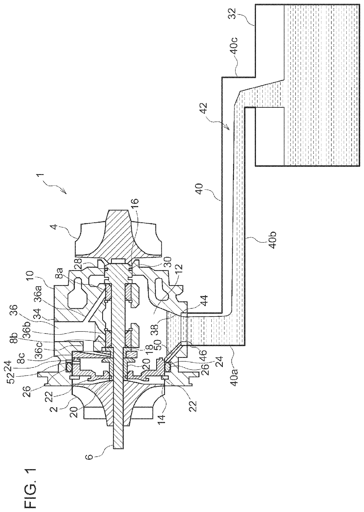
[0062]FIG. 1 is a cross-sectional view illustrating an internal structure of a turbocharger 1 according to the first embodiment of the present invention. The turbocharger 1 is a supercharging device for compressing and supplying (supercharging) intake air taken from outside to a combustion chamber of an internal combustion engine, by rotary-driving a compressor 2 disposed in an intake passage of an internal combustion engine (not depicted). The turbocharger 1 of the present embodiment includes an exhaust turbine 4 disposed in an exhaust passage of an internal combustion engine, and a rotational shaft 6 coupling the exhaust turbine 4 and the compressor 2. When the exhaust turbine 4 is driven by exhaust gas flowing through the exhaust passage, the compressor 2 is driven in conjunction via the rotational shaft 6, and thereby supercharging is performed.

[0063]In the following description, as the turbocharger 1, a supercharging apparatus including the exhaust turbine 4 as described above ...

second embodiment

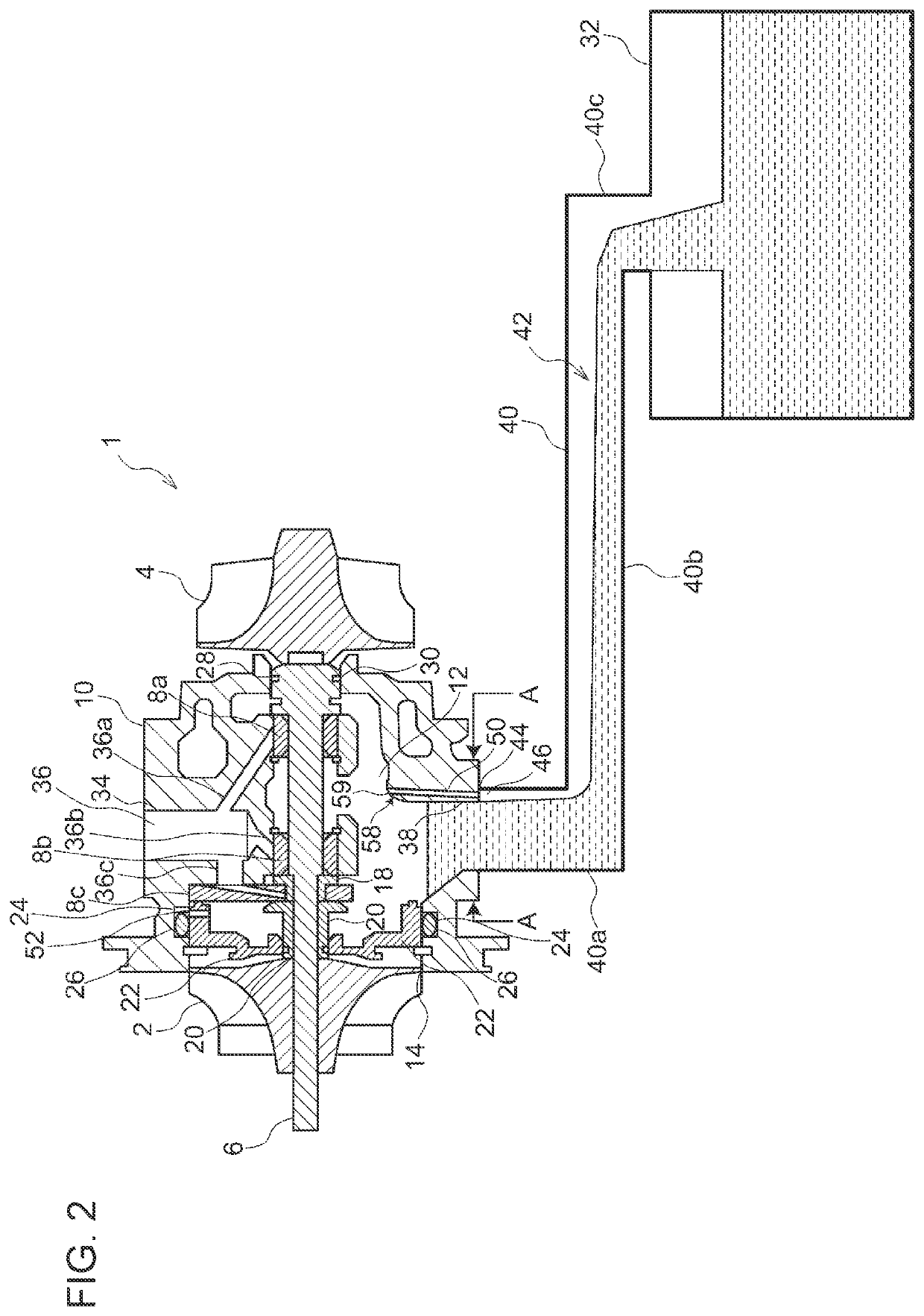
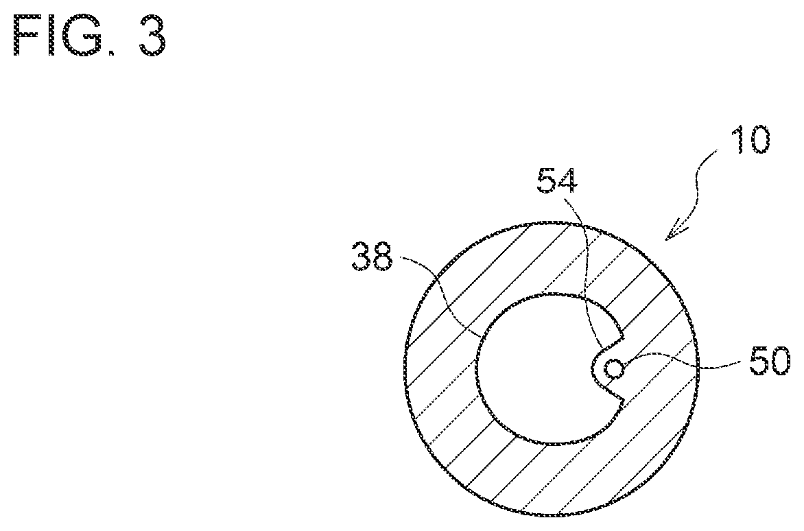
[0077]FIG. 2 is a cross-sectional view illustrating an internal structure of a turbocharger 1 according to the second embodiment of the present invention, and FIG. 3 is a cross-sectional view of FIG. 2 taken along line A-A. In the following description, the same features in the above embodiment are associated with the same reference numerals, and not described again unless otherwise stated.

[0078]In the present embodiment, the air pocket 46 is formed on the curving direction side of the oil discharge pipe 40 on the most upstream portion of the oil discharge pipe 40, and the communication flow passage 50 is formed in the vicinity of the oil discharge port 38 on the curving direction side of the oil discharge pipe 40, of the bearing housing 10, so as to correspond to the air pocket 46. To form such an air pocket 46, as shown in FIG. 3, the oil discharge port 38 has a protruding portion 54 protruding partially toward the curving direction side of the oil discharge pipe 40, and thereby h...

third embodiment

[0081]FIG. 4 is a cross-sectional view illustrating an internal structure of a turbocharger 1 according to the third embodiment of the present invention, and FIG. 5 is a perspective view illustrating only the attachment member 60 of FIG. 4. In the following description, the same features in the above embodiment are associated with the same reference numerals, and not described again unless otherwise stated.

[0082]In the turbocharger 1 according to the present embodiment, the oil discharge port 38 and the uppermost portion of the oil discharge pipe 40 have the substantially same diameter. That is, as described above, the step 44 for forming the air pocket 46 is not provided between the oil discharge port 38 and the uppermost portion of the oil discharge pipe 40, like the typical configuration. In the present embodiment, the turbocharger 1 further includes an attachment member 60 that is attachable to the oil discharge port 38.

[0083]As shown in FIG. 5, the attachment member 60 has a ca...


PUM


Abstract

A turbocharger for supercharging an internal combustion engine includes: a bearing housing which accommodates a bearing supporting a rotational shaft of the turbocharger; an oil discharge port for discharging lubricant oil stored in an internal space of the bearing housing; an air pocket formed in the oil discharge port or an oil discharge pipe connected to the oil discharge port; and a communication flow passage which brings the air pocket and the internal space into communication.

Description

TECHNICAL FIELD[0001]The present disclosure relates to a turbocharger for supercharging an internal combustion engine.BACKGROUND ART[0002]A known turbocharger drives a compressor coupled to a rotational shaft, and thereby supercharges an internal combustion engine. The rotational shaft of the turbocharger is supported rotatably by a bearing accommodated in a casing. The bearing supporting the rotational shaft is housed in a bearing housing, and the bearing housing is supplied with lubricant oil from an oil pan or the like, which lubricates each component.[0003]The lubricant oil used for the bearing is returned to the oil pan, via an oil discharge pipe from an oil discharge port disposed below the bearing housing. Herein, depending on the operation state of the turbocharger, if the internal pressure of the bearing housing, from which the lubricant oil is discharged, becomes lower than the internal pressure of the oil pan, to which the lubricant oil is discharged, discharge of the lub...

Claims


Application Information

Patent Timeline
Patent Type & Authority Patents(United States)
IPC IPC(8): F02B39/14F01D25/16F01D25/18
CPCF02B39/14F01D25/16F01D25/18F05D2220/40F05D2240/55F02B39/00F02B39/005F16C33/6685F16C33/1025F01M2011/021F16C2360/24
Inventor KAGIMOTO, YOSHIMIISHIZAKI, TATSUYAISHII, YUTA
Owner MITSUBISHI HEAVY IND ENGINE & TURBOCHARGER LTD
Why Eureka
Try Eureka