
Variable pre and de-compression control mechanism and method for hydraulic displacement pump

a technology of pre- and decompression control and hydraulic displacement pump, which is applied in the direction of machines/engines, positive displacement liquid engines, liquid fuel engines, etc., can solve the problems of certain operational problems, and achieve the effect of substantially reducing the noise(s) of relative high pressure differentials between the piston chamber and the respective plenum chamber

Active Publication Date: 2021-04-06
VOLVO CONSTR EQUIP AB
View PDF16 Cites 2 Cited by
  • Summary
  • Abstract
  • Description
  • Claims
  • Application Information

AI Technical Summary

Benefits of technology

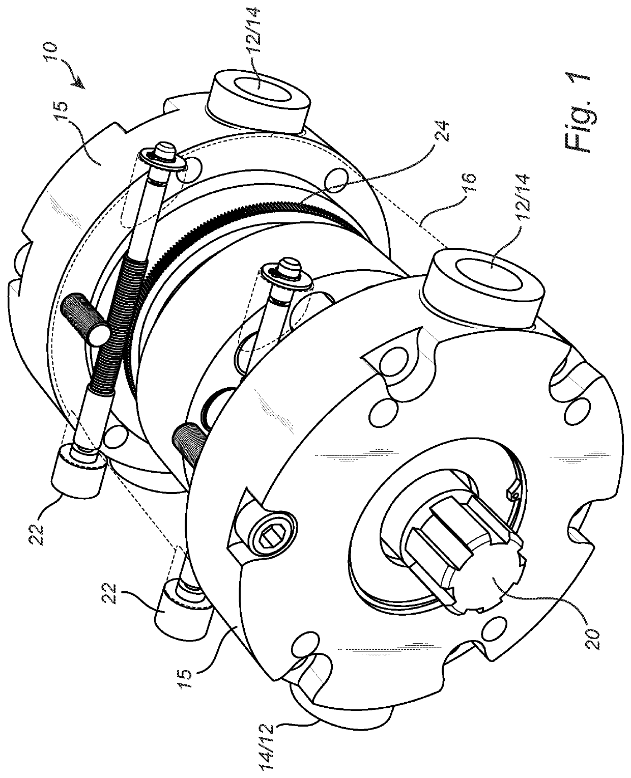
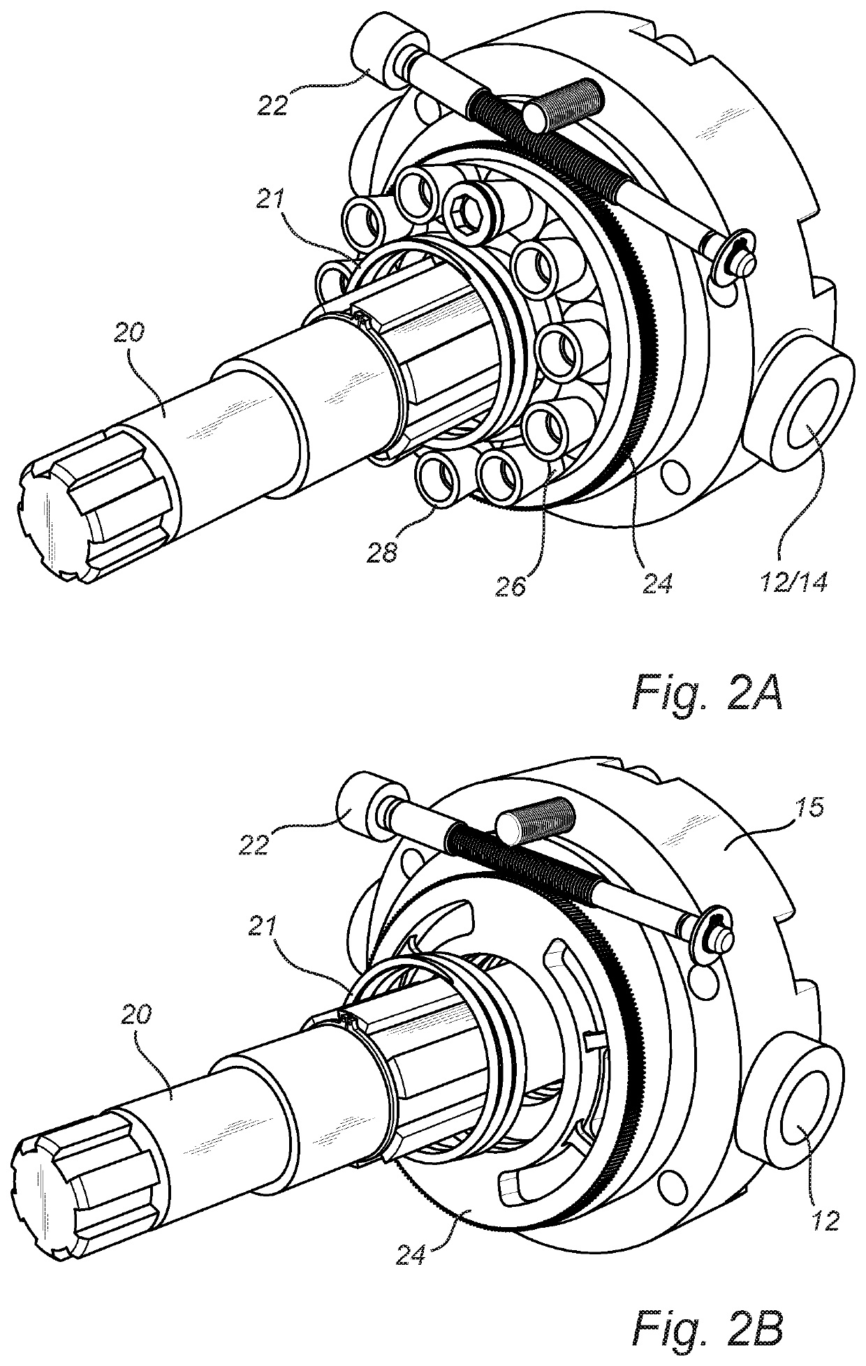
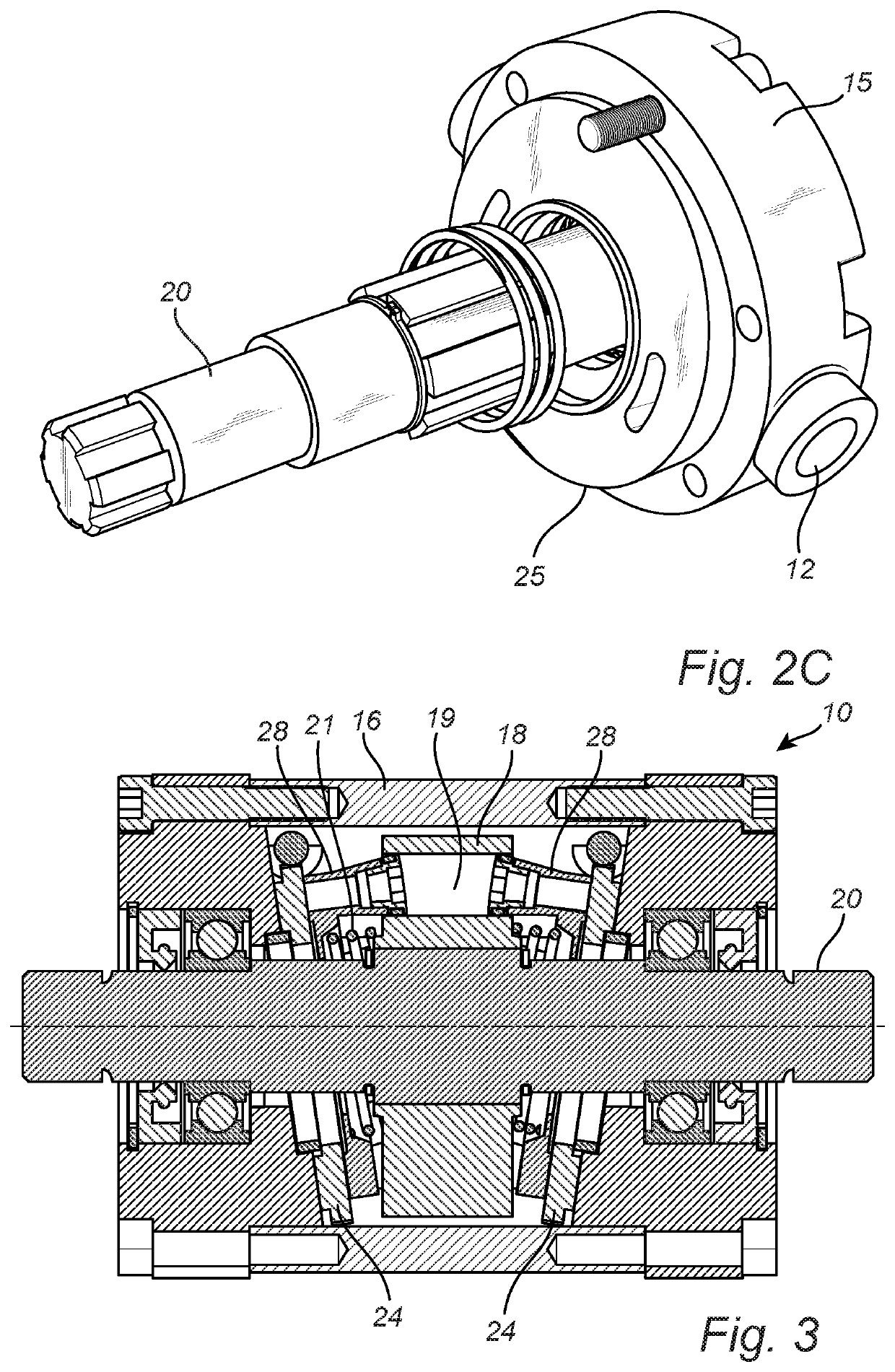
This patent is about a hydraulic displacement pump control system that can change the position of a valve plate to reduce noise and improve pump performance. The valve plate can be moved forward or rearward, in rotation, to control the pump volume and the amount of pre- or de-compression. This mechanism is particularly useful for pumps where the valve plate is retained in a relatively fixed position and only incrementally advanced or retarded in position with respect to the pistons. The changing angle of the valve plates affects its position and function in imparting motion to the pistons, increasing or decreasing its effect on pre and de-compression.

Problems solved by technology

In these type of pumps, certain operational issues can occur.
One of the issues is “noise”.

Method used


Image

  • Variable pre and de-compression control mechanism and method for hydraulic displacement pump
  • Variable pre and de-compression control mechanism and method for hydraulic displacement pump
  • Variable pre and de-compression control mechanism and method for hydraulic displacement pump

Examples


Embodiment Construction

[0020]The exemplary embodiment of the present invention will now be described with the reference to accompanying drawings. The following description of the preferred embodiment is merely exemplary in nature and is in no way intended to limit the invention, its application, or uses.

[0021]For purposes of the following description, certain terminology is used in the following description for convenience only and is not limiting. The characterizations of various components and orientations described herein as being “front,”“back,”“vertical,”“horizontal,”“upright,”“right,”“left,”“side,”“top,”“bottom,”“above,”“below,” or the like designate directions in the drawings to which reference is made and are relative characterizations only based upon the particular position or orientation of a given component as illustrated. These terms shall not be regarded as limiting the invention. The words “downward” and “upward” refer to position in a vertical direction relative to a geometric center of the...


PUM


Abstract

A rotary displacement piston pump is disclosed having rotatable single or dual valve / port plate(s). The valve plate, being rotatable forward and / or rearward with respect to the rotation of the piston carrier, alters the phasing of the land area of the pumping action thereby altering the phasing of piston speed inasmuch as the land area can be moved to a position to accelerate the piston(s) in a pre or decompression phase. In this way, pump noise, from colliding pressure fronts within the respective high and low pressure plenums, can be “tuned” out of the pump by adjusting the phasing and position of the valve plate(s) and raising or lowering the pre and decompression pressure(s) as necessary. Pump volume can also be controlled by advancing or retarding the valve plate(s), either in or out of synch, so as to shorten intake / exhaust piston stroke and overlap fluid flow between respective intake / exhaust plenums.

Description

TECHNICAL FIELD[0001]The invention relates to the field of hydraulic displacement pumps. Specifically, the invention relates to a hydraulic displacement pump including a rotatable valve plate that, upon advancing or retarding movement thereof, can vary pump throughput capacity and the effect(s) of pre and de-compression on pump operational noise.BACKGROUND ART[0002]Swashplate type pumps are known. A series of pistons are actuated by the coordinated engagement of a rotating member that causes the respective discrete pump pistons to engage in successive serial suction / compression strokes as the rotating member spins. The pistons can be mounted so as to spin about a collective axis against a fixed axially tilted plate so as to create piston movement or, the pistons themselves can be rotationally fixed and the tipped actuator can be made to spin and thus axially drive and reciprocate the successive pistons. In either case, a disk-shaped valve plate is present on the suction / compression ...

Claims


Application Information

Patent Timeline
Patent Type & Authority Patents(United States)
IPC IPC(8): F01B3/10F01B3/00
CPCF01B3/0035F01B3/104F04B49/22F04B53/001F04B1/26F04B1/2042F04B1/2035F04B1/0408F04B1/324
Inventor TONNQVIST, ANDREASFORSSELL, JONASPALMBERG, JAN-OVEERICSON, LISELOTTHEDEBJÖRN, ANDERS
Owner VOLVO CONSTR EQUIP AB
Learn More