Boost pressure control

a turbocharged engine and boost pressure technology, applied in the direction of engine controllers, machines/engines, fuel injection control, etc., can solve the problem of very fast control of the boost pressure in the turbocharged engine, and achieve the effect of improving the efficiency of the internal combustion engin

Active Publication Date: 2021-04-06
GE JENBACHER
View PDF11 Cites 0 Cited by
  • Summary
  • Abstract
  • Description
  • Claims
  • Application Information

AI Technical Summary

Benefits of technology

[0005]In transients, by using at least two of the at least two actuating members, the present disclosure enables very fast transient load acceptance and load rejection capability, a key requirement for users in new markets such as peaking and frequency regulation.
[0006]Also, the present disclosure makes it possible to have one of the at least two actuating members (the bypass valve) fully closed during steady-state, thus reducing pumping losses and maximizing engine efficiency.
[0007]The inventive control strategy is robust to sticking of one of the at least to actuating members in closed position since it can smoothly use the other actuating member for boost control and avoid over-boost or turbo over-speed.
[0016]The control device can be adapted to prevent attainment of a surge limit of the turbocharger.
[0020]The control device is adapted to fully close the compressor bypass valve in a stationary state of the internal combustion engine and to control boost pressure by the opening degree of the wastegate only to improve efficiency of the internal combustion engine.

Problems solved by technology

The problem is to control the boost pressure in a turbocharged engine very fast during transients while avoiding surge and over-boost / turbo-over-speed.

Method used


Image

  • Boost pressure control
  • Boost pressure control
  • Boost pressure control

Examples


Embodiment Construction

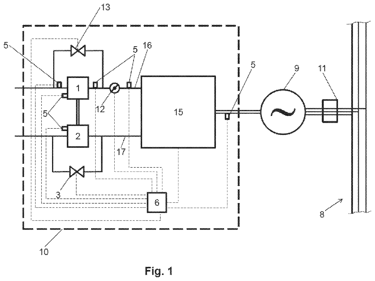
[0034]FIG. 1 shows an internal combustion engine 10 having a plurality of combustion chambers 15 comprising a (single-stage) turbocharger which has a compressor 1 arranged in an intake manifold 16 and an exhaust gas turbine 2 arranged in an exhaust manifold 17. The compressor 1 can be bypassed using a bypass around the compressor 1. The extent of bypassing can be controlled depending on a degree of opening of a compressor bypass valve 13. The exhaust gas turbine 2 can be bypassed using a bypass around the exhaust gas turbine 2. The extent of bypassing can be controlled depending on a degree of opening of a wastegate 3.

[0035]The internal combustion engine 10 is in this embodiment part of a genset further comprising a generator 9 to which the internal combustion engine 10 is mechanically coupled. The generator 9 is coupled to a power supply network 8 having three phases. The connection to the power supply network 8 can be controlled by network switch 11.

[0036]The control device 6 is c...


PUM


Abstract

An internal combustion engine is provided having at least one turbocharger having a compressor and an exhaust gas turbine, at least two actuating members for controlling a boost pressure by the compressor, a measuring device for measuring at least one measurement signal, and a control device adapted to actuate the actuating members by varying a degree of opening of the actuating members. The control device of the internal combustion engine is configured to calculate a total degree of opening of the actuating members necessary to achieve a desired boost pressure provided by the compressor. This is in dependence on the at least one measurement signal. The control device is also configured to determine the total degree of opening split between each of the at least two actuating members, and to control each of the actuating members according to its individual degree of opening to reach the desired boost pressure.

Description

TECHNOLOGY FIELD[0001]The present disclosure concerns an internal combustion engine with the features of the preamble of claim 1, a genset comprising such an internal combustion engine and a method of operating an internal combustion engine with the features of the preamble of claim 14.BACKGROUND OF THE DISCLOSURE[0002]Turbochargers are used in order to boost pressure of air, a mixture of fuel and air or pure fuel before delivery to combustion chambers of the internal combustion engine.[0003]An internal combustion engine with the features of the preamble of claim 1 is shown in U.S. Pat. No. 6,134,888.BRIEF DESCRIPTION OF THE DISCLOSURE[0004]The problem is to control the boost pressure in a turbocharged engine very fast during transients while avoiding surge and over-boost / turbo-over-speed. If one of the at least two actuating members is a compressor bypass valve it is preferred to have such a control strategy that the compressor bypass valve remains closed to the maximum extent poss...

Claims


Application Information

Patent Timeline
Patent Type & Authority Patents(United States)
IPC IPC(8): F02B37/18F02B37/16F02D29/06F02D41/00F02B37/013F02B37/22
CPCF02B37/18F02B37/013F02B37/16F02B37/162F02B37/22F02D29/06F02D41/0007F02D2200/0406F02D2200/101F02B37/183Y02T10/12
Inventor SRINIVASAN, PRASHANTLU, HANGKUMAR, CHANDANR., KARTHIKK
Owner GE JENBACHER
Why Eureka
Try Eureka