Measurement system and method for multiple antenna measurements with different angles of arrival

a measurement system and antenna technology, applied in the direction of electronic circuit testing, measurement instrument housing, antennas, etc., can solve the problems of limiting the accuracy and functionality of testing methods and devices, and achieve the effects of enhancing efficiency, reducing complexity, and increasing efficiency

Active Publication Date: 2021-04-06
ROHDE & SCHWARZ GMBH & CO KG
View PDF6 Cites 7 Cited by
  • Summary
  • Abstract
  • Description
  • Claims
  • Application Information

AI Technical Summary

Benefits of technology

[0006]Embodiments of the present disclosure provide, according to the first aspect of the invention, a measurement system comprising inside an anechoic chamber: a device under test, several measurement antennas, several mirrors, and at least one shaped reflector. The measurement antennas are placed pointing at the shaped reflector. Further, there are several mirrors placed along fields created by the shaped reflector wherein the mirrors reflect fields that form different angles of arrival at the device under test. Advantageously, fast switching of angles of arrival at the device under test can be achieved, thereby ensuring a realistic measurement with high accuracy. Further advantageously, the use of the reflector allows for creating large quiet zones, reducing the required measurement space.
[0007]According to a first preferred implementation form of the first aspect of the invention, each of the several measurement antennas is a feed antenna. In addition to this or as an alternative, the shaped reflector corresponds to a compact antenna test range reflector. Moreover, the anechoic chamber is a shielded anechoic chamber which additionally or alternatively is of cuboid shape. Advantageously, measurement accuracy and measurement efficiency can be enhanced. Further advantageously, complexity can further be reduced.
[0008]According to a second preferred implementation form of the first aspect of the invention, the measurement antennas are set at different angles whereby the measurement antennas pointing at the shaped reflector are at an offset distance from the focal point of the shaped reflector. In addition to this, or as an alternative, the field generated by each of the measurement antennas pointing at the reflector is off center. Advantageously, for instance, measurement efficiency can further be increased.

Problems solved by technology

It is noted, nevertheless, that said prior art document does not envisage radiation at the DUT having several different angles of arrival, neglecting the possible dynamical changing behavior of the antennas during operation, and then limiting the accuracy and functionality of the testing method and device.

Method used


Image

  • Measurement system and method for multiple antenna measurements with different angles of arrival
  • Measurement system and method for multiple antenna measurements with different angles of arrival
  • Measurement system and method for multiple antenna measurements with different angles of arrival

Examples


Embodiment Construction

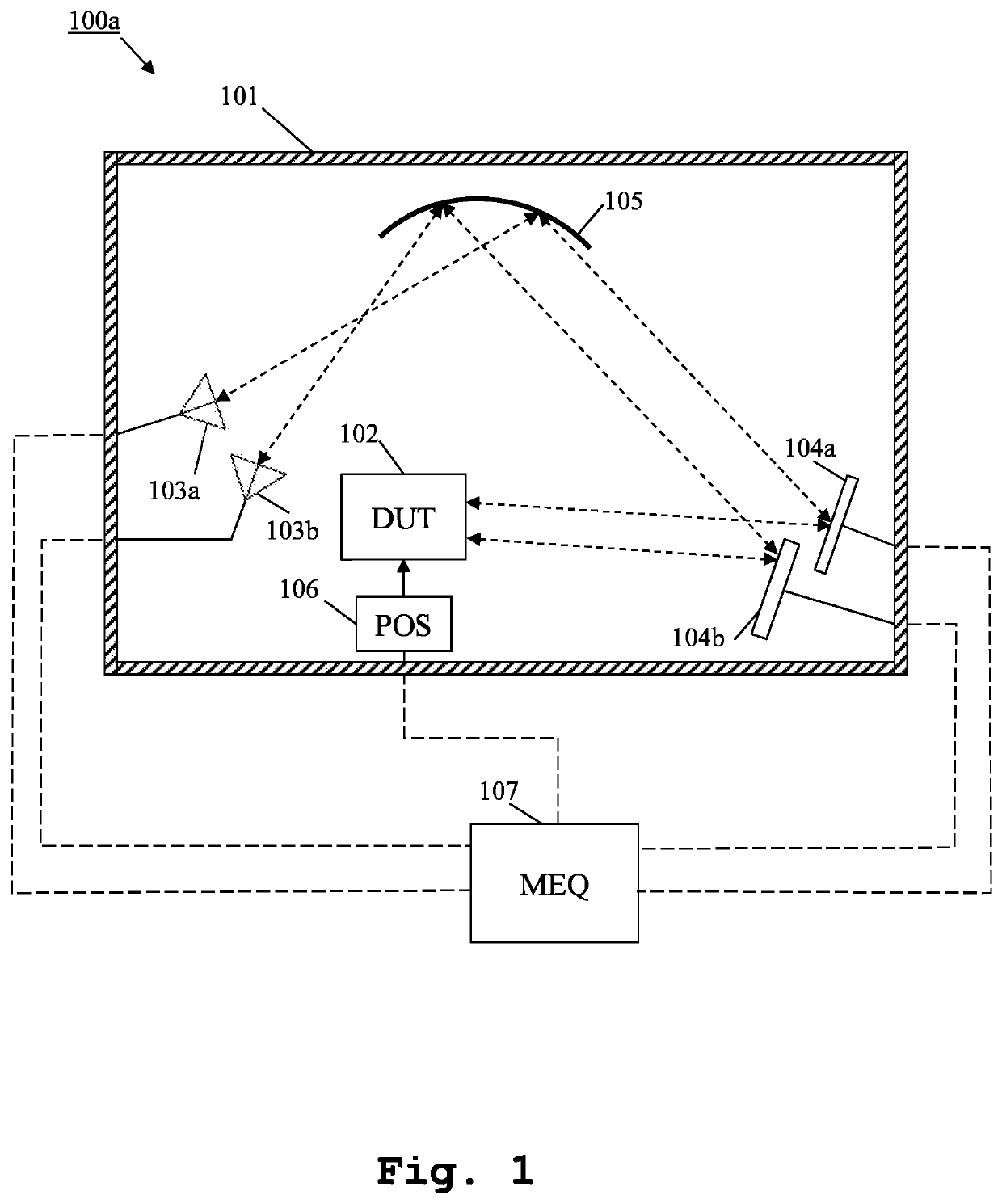
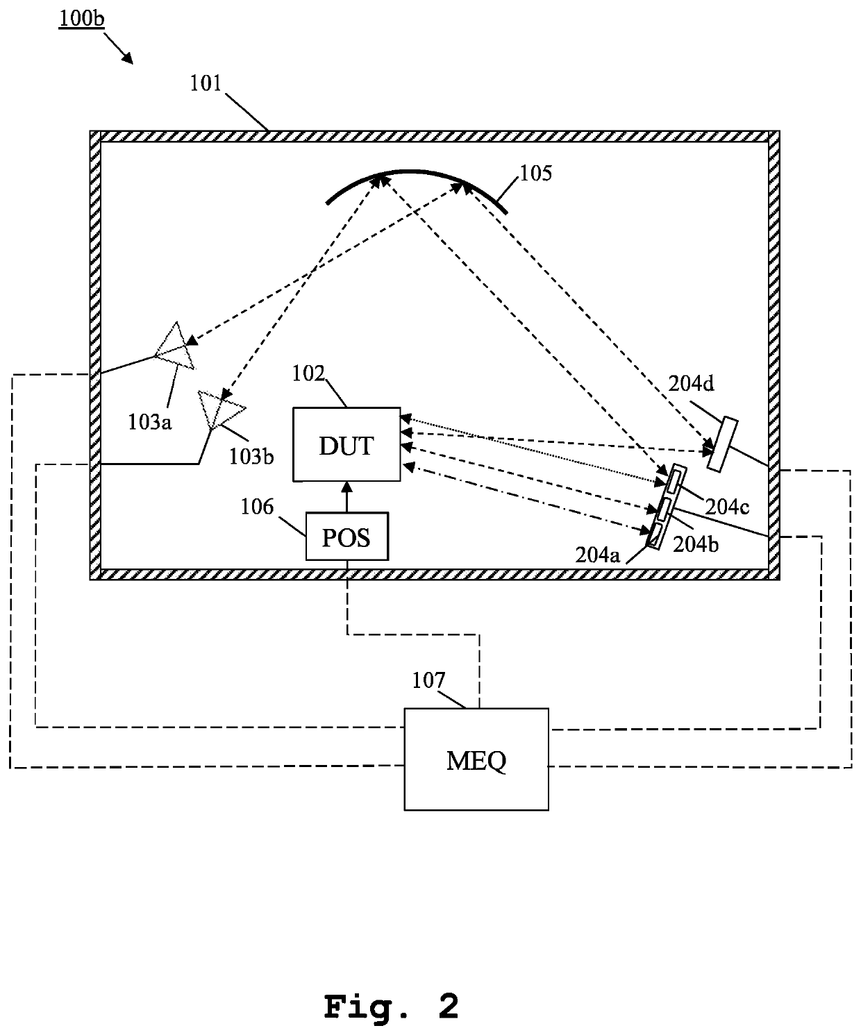
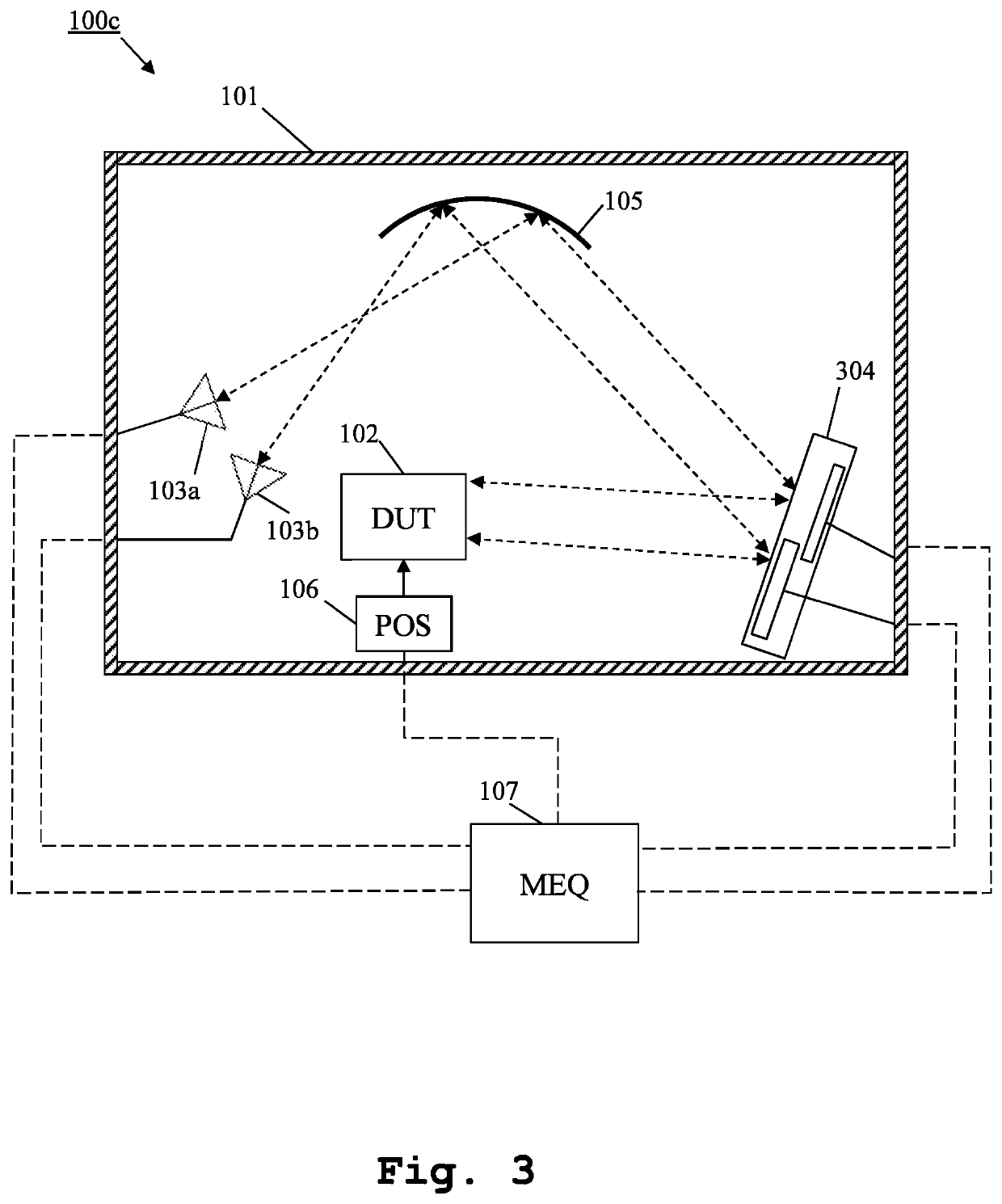
[0032]Firstly, FIG. 1 depicts an exemplary embodiment of an inventive measurement system 100a. The measurement system 100a comprises, inside an anechoic chamber 101, a device under test 102, several measurement antennas, exemplarily two measurement antennas 103a, 103b, several mirrors, exemplarily two mirrors 104a, 104b, at least one shaped reflector 105, and a positioner 106 for positioning the device under test 101.

[0033]In this exemplary case, each of the measurement antennas 103a, 103b is also a feed antenna. Furthermore, the shaped reflector 105 corresponds to a compact antenna test range reflector. In this context, it should be mentioned that if one of the several antennas corresponds to the normal compact antenna test range feed (CATR) antenna located at the focal point of the reflector, then the number of measurement antennas is the total number of antennas N but one, where N is a natural number, whereas if there is not a feed antenna located at the focal point of the reflec...


PUM


Abstract

A measurement system and method for over the air multiple antennas measurements are provided. The measurement system comprises, inside an anechoic chamber, a device under test, several measurement antennas, several mirrors and at least one shaped reflector. The measurement antennas are placed pointing at the shaped reflector. Each of the mirrors is placed along fields reflected by the shaped reflector. The mirrors reflect fields that form different angles of arrival at the device under test.

Description

TECHNICAL FIELD[0001]The invention relates to a measurement system and a measurement method for multiple antenna measurements in the far-field regime, within a compact antenna test range reflector chamber.BACKGROUND OF THE INVENTION[0002]The rapidly evolving field of wireless communications employing multiple antennas, such as Multiple-Input Multiple-Output (MIMO) systems, is generating an enormous amount of wireless applications, demanding for versatile measurement systems and measurement methods to verify the correct performance of said technologies in a practical, highly efficient and accurate manner, primarily with regard to their far-field characteristics.[0003]US 2018 / 0006745 A1 discloses a system for characterizing a device under test (DUT) including an integrated antenna array. In particular, the system includes an optical subsystem with first and second focal planes, and the integrated antenna array is positioned substantially on the first focal plane of the optical subsyst...

Claims


Application Information

Patent Timeline
Patent Type & Authority Patents(United States)
IPC IPC(8): G01R31/302H01Q15/14G01R1/04G01R31/28G01R31/303G01R31/311
CPCG01R31/3025G01R1/04G01R31/2822G01R31/303G01R31/311H01Q15/14H01L2224/48227H01L2224/73265H01L2924/00H01L2924/0002G01R29/0871
Inventor ROWELL, CORBETT
Owner ROHDE & SCHWARZ GMBH & CO KG
Why Eureka
Try Eureka