
Apparatus and method for fabricating high strength long nanostructured tubes

a nanostructured tube, high-performance technology, applied in the field of fabricating nanostructured tubes, can solve the problems of increasing manufacturing time and labor intensity, inhomogeneous deformation and even folding of processed materials, and methods that present some problems/limitations, so as to prevent the creation of friction forces, eliminate an additional amount of resistance forces, and eliminate additional amounts of resistance forces

Active Publication Date: 2021-04-20
FARAJI GHADER +1
View PDF12 Cites 0 Cited by
  • Summary
  • Abstract
  • Description
  • Claims
  • Application Information

AI Technical Summary

Benefits of technology

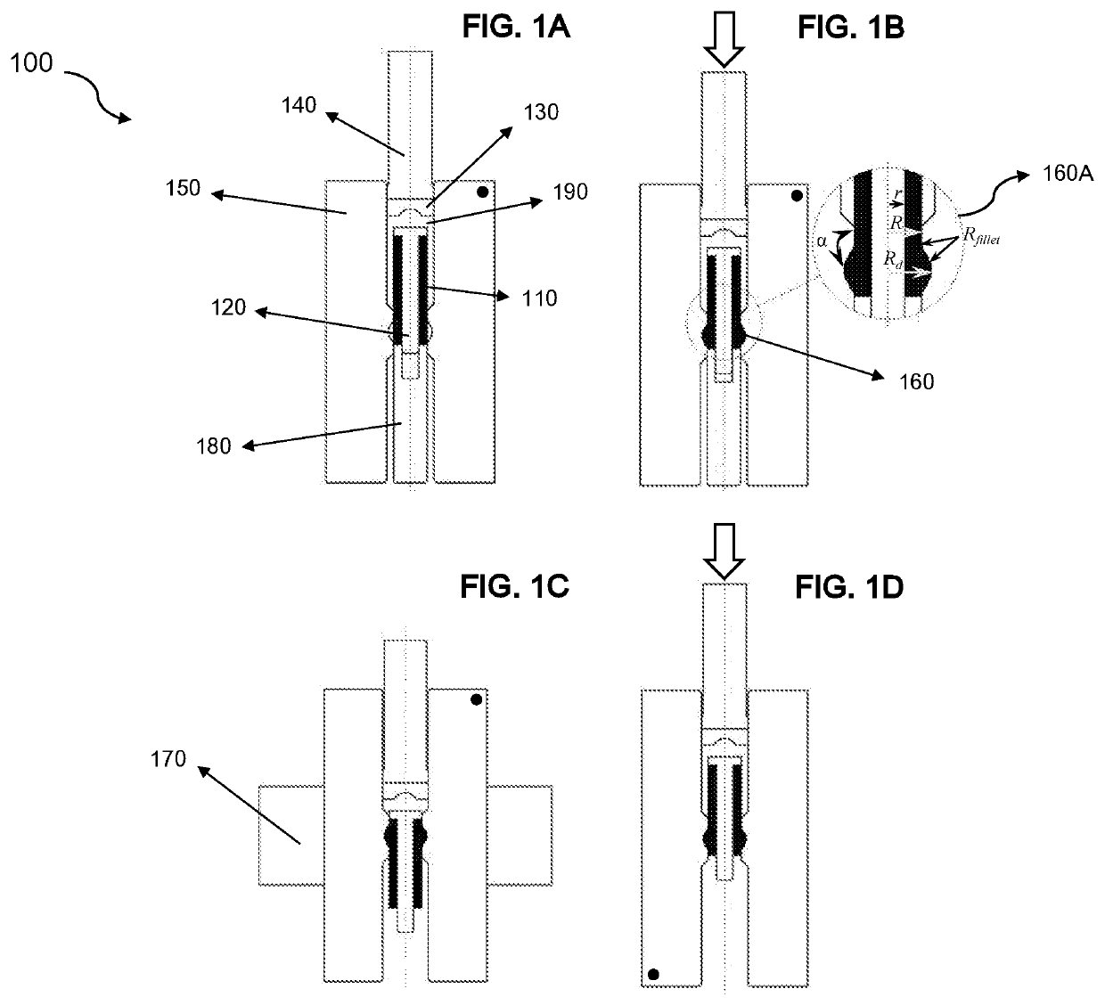
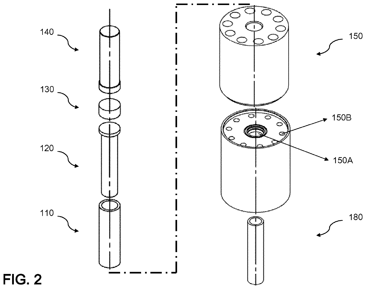
This patent describes a method of extruding samples using a moving mandrel and a sample billet, which can simultaneously move in a cooperative manner. This movement can zero out a relative velocity between the sample billet and the moving mandrel, reducing friction and resistant force against the sample during extrusion. A lubricant material can also apply a hydrostatic pressure to the sample billet, further reducing the required force for the punch box to push the sample through the die unit during extrusion. The applied strain during each extrusion cycle can severely deform the sample billet and refine its nanostructure, resulting in an ultrafine grained tube with high mechanical strength and long length.

Problems solved by technology

Despite powerful tools for processing UFG / NG materials, these methods present some problems / limitations.
For example, a restriction in size and a need for applying external back pressure usually require a complicated heavy and long machinery in SDP processes, and thus resultant deformations in the fabricated materials are not steady, which can lead to inhomogeneous deformation and even folding of the processed materials.
Consequently, the entire process can lead to increase in manufacturing time and labor intensity, and thus cost inefficiency.

Method used


Image

  • Apparatus and method for fabricating high strength long nanostructured tubes
  • Apparatus and method for fabricating high strength long nanostructured tubes
  • Apparatus and method for fabricating high strength long nanostructured tubes

Examples


Embodiment Construction

[0019]In the following detailed description, numerous specific details are set forth by way of examples in order to provide a thorough understanding of the relevant teachings. However, it should be apparent to those skilled in the art that the present teachings may be practiced without such details. In other instances, well known methods, procedures, components, and / or circuitry have been described at a relatively high-level, without detail, in order to avoid unnecessarily obscuring aspects of the present teachings. As part of the description, some of this disclosure's drawings represent structures and devices in block diagram form in order to avoid obscuring the invention. In the interest of clarity, not all features of an actual implementation are described in this specification. Moreover, the language used in this disclosure has been principally selected for readability and instructional purposes, and may not have been selected to delineate or circumscribe the inventive subject m...


PUM

PropertyMeasurementUnit
tensile strengthaaaaaaaaaa

Abstract

An improved apparatus and method of fabricating long nanostructured or ultrafine grained tubes includes, in one implementation, expanding and extruding a sample material through cyclic deformations. The first cycle begins with expanding the sample through a die unit by applying pressure using a punch box, then with extruding the sample by applying back pressure using a stationary mandrel, which in turn reduces the expanded sample diameter to the original diameter. The next cycle begins with inverting the die unit to further extrude the sample with no need to apply back pressure. Furthermore, resistant forces against the sample are reduced by using a lubricant material inside the die unit, thus allowing continuation of additional cycles without constraining the sample length, resulting in desired strength and elongation.

Description

CROSS REFERENCE TO RELATED APPLICATION[0001]This application claims the benefit of priority to Iran Application Serial Number 139650140003002419, filed on May 24, 2017, the entire content of which is incorporated herein by reference.TECHNICAL FIELD[0002]The present disclosure relates generally to fabricating nanostructured tubes and, more particularly, to improved apparatus for and method of fabricating high strength, long nanostructured tubes.BACKGROUND[0003]Over the past decade, severe plastic deformation (SPD) processes have revealed a significant promise in fabricating ultrafine grained (UFG) and nano-grained (NG) materials with superior and unique mechanical and physical properties. The main objective of a SPD process is to fabricate improved materials with better reliability and environmental compatibility. Such property improvements include higher strength, higher ductility, higher corrosion resistance, and / or super plasticity.[0004]Recent development in the field of SPD proc...

Claims


Application Information

Patent Timeline
Patent Type & Authority Patents(United States)
IPC IPC(8): B21C23/08B21C23/00B21C23/32
CPCB21C23/085B21C23/001B21C23/32
Inventor FARAJI, GHADERMOTALLEBI SAVARABADI, MOHAMMAD
Owner FARAJI GHADER
Learn More