Voltage control circuit and voltage control method
- Summary
- Abstract
- Description
- Claims
- Application Information
AI Technical Summary
Benefits of technology
Problems solved by technology
Method used
Image
Examples
Embodiment Construction
[0017]In following descriptions, different embodiments are provided to explain the concept of the present invention. Please note, the terms “first”, “second” . . . and the like are only for identifying different components and steps, but do not mean to limit sequences thereof.
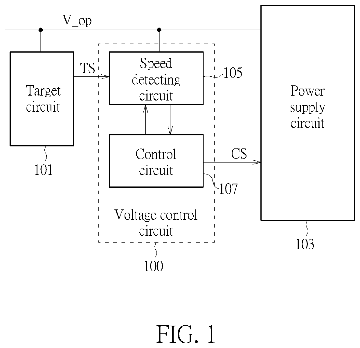
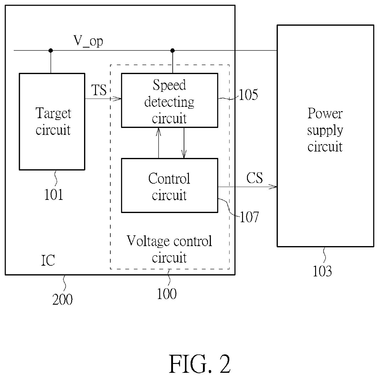
[0018]FIG. 1 is a block diagram illustrating a voltage control circuit 100 according to one embodiment of the present invention. As shown in FIG. 1, the voltage control circuit 100 is coupled to a target circuit 101 and a power supply circuit 103 configured to generate an operating voltage V_op to the target circuit 101. The voltage control circuit 100 comprises a speed detecting circuit 105 and a control circuit 107. The speed detecting circuit 105 can receive a test signal TS from the target circuit 101 and calculate an operating speed (for example, the clock rate) of the target circuit based on the test signal TS. In one embodiment, the test signal TS is a clock signal corresponding to the operating speed of...
PUM
 Abstract
Description
Claims
Application Information
 - R&D
- Intellectual Property
- Life Sciences
- Materials
- Tech Scout
- Unparalleled Data Quality
- Higher Quality Content
- 60% Fewer Hallucinations
Browse by: Latest US Patents, China's latest patents, Technical Efficacy Thesaurus, Application Domain, Technology Topic, Popular Technical Reports.
© 2025 PatSnap. All rights reserved.Legal|Privacy policy|Modern Slavery Act Transparency Statement|Sitemap|About US| Contact US: help@patsnap.com


