Contactless inductive energy transmission device and method

Active Publication Date: 2021-04-20
WEIDMULLER INTERFACE GMBH & CO KG
View PDF18 Cites 6 Cited by
  • Summary
  • Abstract
  • Description
  • Claims
  • Application Information

AI Technical Summary

Benefits of technology

[0007]It is an object of the present invention to extend the application possibilities of such a device for contactless energy transmission, especially for use in automation.
[0008]A device of the type mentioned above is characterized by the fact that the primary portion and the secondary portion each have a data transmission unit for transmitting data via the air gap. Especially when used in the automation sector in an industrial environment, a data connection is often required in addition to the supply current, e.g. for the interchangeable tool of a robot arm. The transmission of power and data together through a single device with only one primary and one secondary portion simplifies setup and maintenance of the device.
[0012]According to another embodiment of the device, the data transmission units each have one light-conducting element. Preferably, this element is mainly cylindrical in shape and has a first light entry or exit surface facing the transmitting or receiving elements and a second light entry or exit surface facing the air gap. The first light entry or exit surface and / or the second light entry or exit surface are planar, concave or convex in shape. The light-conducting elements support the efficiency of the transmission and enable transmission even in the presence of a lateral offset and / or a distance variation between the primary and secondary portions. In addition, the coil center has limited installation space. The light-conducting element can be cylindrical with a diameter that fits snugly into the center of the coil. A larger installation space is then available outside the coil for the transmitting element and the receiving element. The first light entry and exit surface is planar and the second light entry and exit surface concave in design, which is particularly advantageous with regard to compensating for lateral offset.

Problems solved by technology

The danger of arcs forming when disconnecting connectors with a high current load is also not present with contactless devices for energy transmission.

Method used


Image

  • Contactless inductive energy transmission device and method
  • Contactless inductive energy transmission device and method
  • Contactless inductive energy transmission device and method

Examples


Embodiment Construction

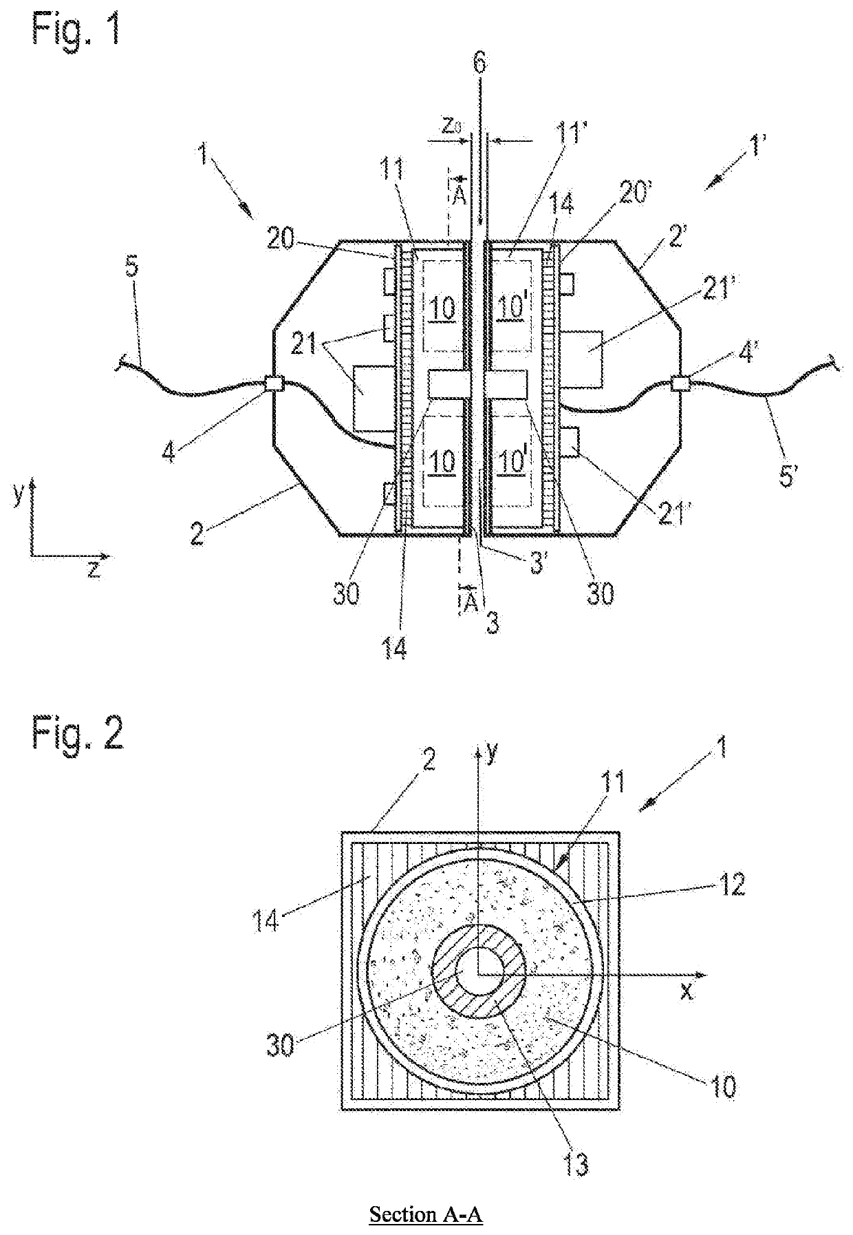
[0022]FIG. 1 is a schematic sectional view of a device for contactless energy transmission from a primary portion 1 to a secondary portion 1′ in accordance with the invention. In FIG. 2, the primary portion 1 is illustrated in a section along the section line A-A displayed in FIG. 1.

[0023]In this description and in the drawing, elements which are assigned to primary portion 1, also called primary elements below, bear reference numerals without apostrophe in the figures. Elements assigned to secondary portion 1, also called secondary elements below, bear reference numerals with a corresponding apostrophe, whereby primary and secondary elements which have the same or a comparable function are provided with reference numerals with the same numbers. If the following does not explicitly refer to the primary or secondary side, reference numerals without an apostrophe are used that refer to both sides.

[0024]Primary portion 1 and secondary portion 1 each have a housing 2, which can be made ...


PUM

PropertyMeasurementUnit
frequencyaaaaaaaaaa
diameteraaaaaaaaaa
energyaaaaaaaaaa

Abstract

A contactless inductive energy transmission device includes a primary and a secondary each having at least one coil. The coils are inductively coupled via an air gap. The primary and the secondary each also have a data transmission unit for the transmission of data via the air gap.

Description

[0001]This application is based on PCT EP2017 / 075324 filed Oct. 5, 2017 which claims priority of DE 10 2016 119 213.9 filed Oct. 10, 2016 and DE 10 2017 101 891.3 filed Jan. 31, 2017 / The entire contents of these applications are incorporated herein by reference.BACKGROUND OF THE INVENTION[0002]The invention relates to a device for contactless inductive energy transmission from a primary portion to a secondary portion, each having at least one coil, which can be inductively coupled to one another via an air gap. The invention further relates to an operating method for a device for contactless inductive energy transmission from the coil of a primary portion to the coil of a secondary portion.[0003]In contrast to connectors in which energy is transmitted via mechanically connected or disconnected contact elements, devices for contactless energy transmission benefit with regard to wear due to a high number of mating cycles or strong vibrations. In addition, contact erosion is prevented ...

Claims


Application Information

Patent Timeline
Patent Type & Authority Patents(United States)
IPC IPC(8): H01F38/14H02J50/10G02B6/24H04B5/00
CPCH01F38/14G02B6/24H02J50/10H04B5/0031H04B5/0037H01R24/00
Inventor GRÜNBERG, OLAFNEU, MARC
Owner WEIDMULLER INTERFACE GMBH & CO KG
Why Eureka
Try Eureka