Long-distance fiber optic distributed acoustic sensing amplification system and method thereof

a technology of distributed acoustic sensing and long-distance fiber optics, applied in the direction of instruments, lasers, using wave/particle radiation means, etc., can solve the problem of low optical signal-to-noise ratio (osnr), the power of the probe pulse light must be limited, and the power of the probe pulse light is still exponentially attenuated

Active Publication Date: 2021-04-20
UNIV OF ELECTRONICS SCI & TECH OF CHINA
View PDF6 Cites 1 Cited by
  • Summary
  • Abstract
  • Description
  • Claims
  • Application Information

AI Technical Summary

Benefits of technology

[0006]An object of the present invention is to provide a long-distance FODAS amplification system and a method thereof, for overcoming the problem that the existing FODAS system is difficult to achieve distributed sensing over longer distance.
[0011]Preferably, the long-distance FODAS amplification system further comprises: a remote pump amplifying unit, which comprises an active fiber disposed in the middle of the LEAF; wherein the pump is injected into the active fiber to provide more gain for the probe pulse light, thereby prolonging sensing distance.
[0016]2) transmitting the pump light and the probe pulse light output by the circulator into a LEAF through a WDM to perform distributed amplification, so as to increase the intensity of Rayleigh backscattered light; and
[0033]1. The present invention performs distributed amplification of the LEAFFODAS system, and uses distributed amplification or combination of distributed amplification and ROPA to provide sufficient gain for the probe pulse light transmitted in the LEAF, so as to overcome the fiber loss, change the power distribution of the probe pulse light along the sensing fiber, and improve the probe pulse power at the low-power position, thereby greatly extending the sensing distance of the FODAS system.
[0034]2. The present invention uses LEAF as the sensing fiber of the system, which reduces the transmission loss of the probe pulse light in the sensing fiber, increases the nonlinear effect threshold in the sensing fiber, and increases the input power of the probe pulse light. As a result, the power of the probe pulse light entering the sensing fiber can be increased without sacrificing spatial resolution, thereby increasing the intensity of the Rayleigh backscattered light with higher OSNR and effectively extending the sensing distance of the FODAS system.
[0035]3. The present invention performs amplification for probe pulse light through the co-pumped or the bi-directional distributed amplification with the help of the nonlinear effects, so as to provide sufficient gain to overcome the fiber loss. Meanwhile, the pump light is injected into the active fiber used for ROPA and excites doped particles to provide more gain for amplifying the probe pulse light, which further increases the power of the probe pulse light at the low-power position, thereby prolonging the sensing distance.

Problems solved by technology

When the peak power of the probe pulse light exceeds the nonlinear effect threshold of SMF, the energy of probe pulse light will transfer to the nonlinear scattering, resulting in low optical signal-to-noise ratio (OSNR).
Therefore, the probe pulse light power injected into the sensing fiber must be limited.
However, influenced by fiber loss and Rayleigh scattering, the power of the probe pulse light is still exponentially attenuated during transmission along the fiber, and the sensing distance is limited.
While, if the incident power of the probe pulse light is too high, nonlinear effects will also occur.
Therefore, the conventional LEAF fiber optic distributed acoustic sensing (LEAFFODAS) system is difficult to achieve distributed sensing over longer distance.

Method used


Image

  • Long-distance fiber optic distributed acoustic sensing amplification system and method thereof
  • Long-distance fiber optic distributed acoustic sensing amplification system and method thereof
  • Long-distance fiber optic distributed acoustic sensing amplification system and method thereof

Examples


embodiment 1

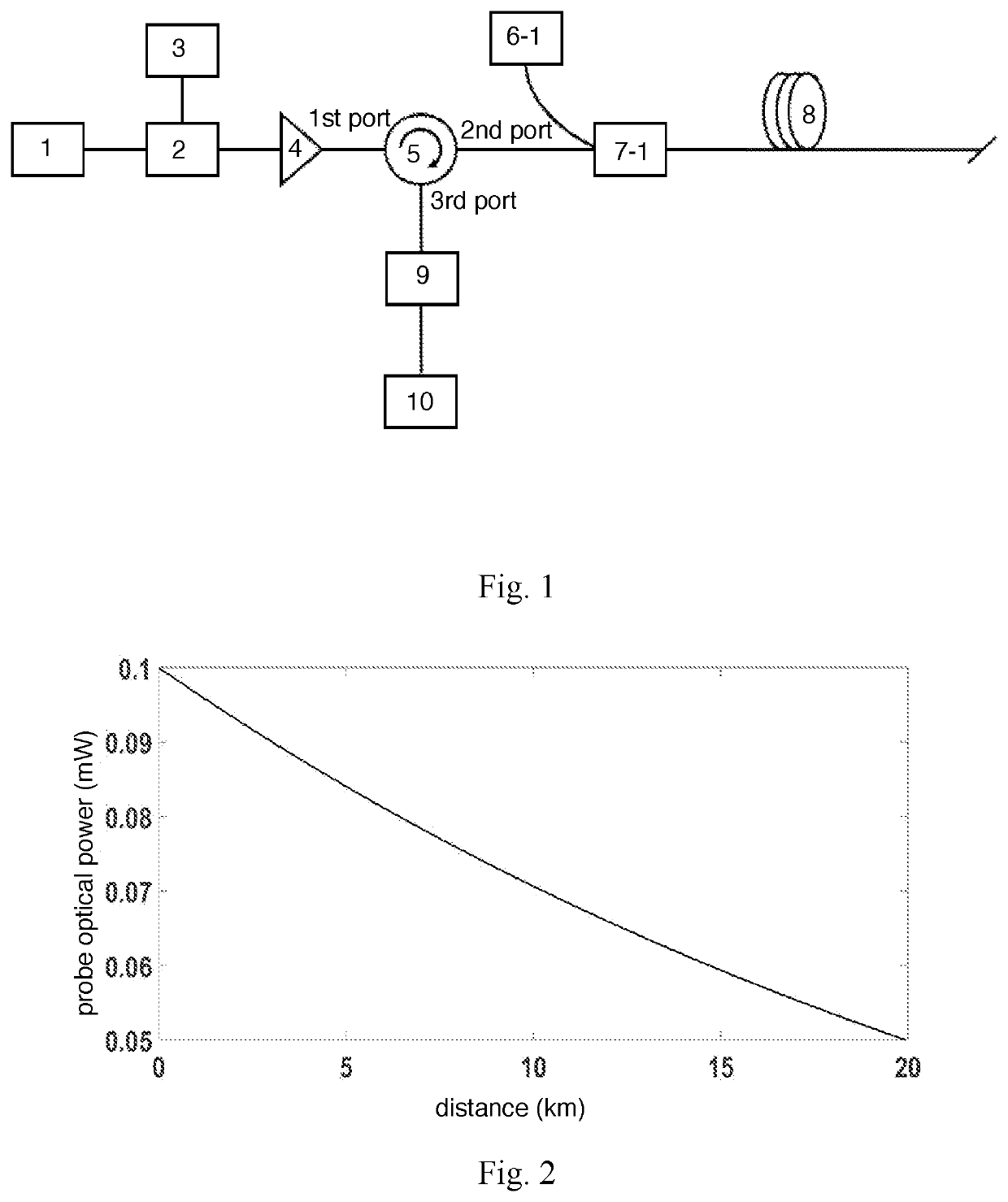
[0082]As shown in FIG. 1, distributed amplification based on a LEAFFODAS system adopts distributed Raman amplification, wherein a pump adopts a Raman pump A 6-1, and a WDM adopts a WDM A 7-1. According to the embodiment 1, co-pumped distributed Raman amplification is used. The probe pulse light enters the WDM A 7-1 through the second port of a circulator 5, while the pump light of the Raman pump A 6-1 enters the WDM A 7-1. The pump light and the probe pulse light enter LEAF 8 through the WDM A 7-1 for determining whether the power of pump light reaches nonlinear effect threshold, wherein if so, the pump light energy transfers to the probe pulse light, and after the pump light energy is completely transferred to the probe pulse light, the probe pulse light transmits to the end of the fiber with attenuation, so as to obtain power-raised Rayleigh backscattered light and complete co-pumped distributed amplification; if not, amplifying is impossible. Referring to FIG. 3, forward Raman pu...

embodiment 2

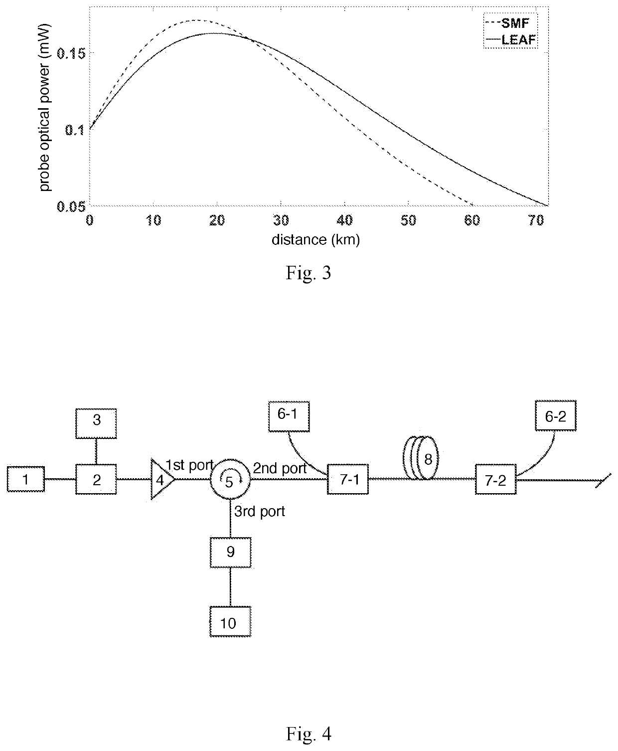
[0083]As shown in FIG. 4, distributed amplification based on a LEAFFODAS system adopts distributed Raman amplification, wherein a pump adopts a Raman pump A 6-1 and a Raman pump B 6-2, and a WDM adopts a WDM A 7-1 and a WDM B 7-2. According to the embodiment 2, bi-directional distributed Raman amplification is used. Power distribution of the probe pulse light along the fiber is shown by a solid line in FIG. 5. Bi-directional distributed amplification comprises steps of: using pump light of the Raman pump A 6-1 as a forward pump; guiding the forward pump and the probe pulse light into the LEAF 8 through the WDM A 7-1, and determining whether the power of forward pump reaches nonlinear effect threshold. If the pump power is enough, then the energy will be transferred to the probe pulse light. After getting gain from forward pump, the probe pulse light is power-increased and keeps transmitting, thus completing forward pump distributed amplification. The pump light of the pump B 6-2, as...

embodiment 3

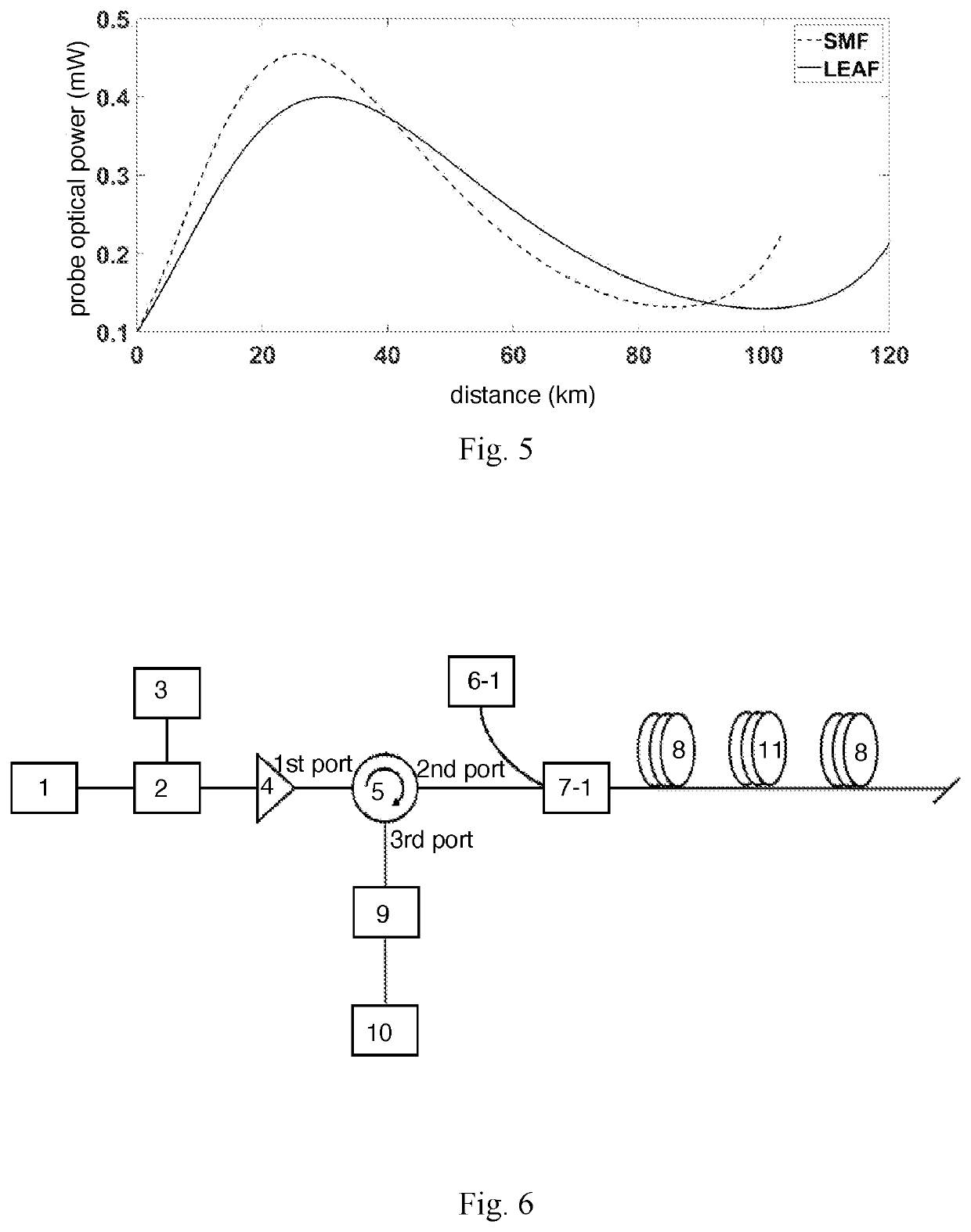
[0084]Distributed amplification based on a LEAFFODAS system adopts distributed Raman amplification, wherein an active fiber used for ROPA adopts EDF 11, a pump adopts a Raman pump A 6-1, and a WDM adopts a WDM A 7-1. According to the embodiment 3, the combination of co-pumped distributed amplification and ROPA is used, a structural view of a corresponding LEAFFODAS system is shown in FIG. 6. After the pump light of the Raman pump A 6-1 and the probe pulse light enter the LEAF 8 through the WDM A 7-1, the pump light energy transfers to the probe pulse light due to stimulated Raman scattering, providing gain to the probe pulse light and increasing power thereof. After the pump light is consumed, the gain of the probe pulse light is reduced, then the power is reduced. Before the pump light is completely consumed, residual pump light injects into the active fiber, namely the EDF 11, so as to excites active ions in the EDF 11, thereby providing additional gain for the probe pulse light. ...


PUM


Abstract

A long-distance FODAS amplification system includes a distributed amplification unit, which includes a LEAF, a pump, and a WDM; wherein the pump light passes through the WDM into the LEAF, so as to realize distributed amplification. A long-distance FODAS amplification method includes steps of: 1) modulating and amplifying a light source to obtain the probe pulse light; 2) guiding the pump light and the probe pulse light into LEAF; 3) combining the probe pulse light with the pump light to perform distributed amplification, so as to generate power-raised Rayleigh backscattered light; and 4) converting and demodulating the Rayleigh backscattered light after being output through the circulator, so as to complete distributed sensing.

Description

CROSS REFERENCE OF RELATED APPLICATION[0001]The present invention claims priority under 35 U.S.C. 119(a-d) to CN 201910101194.7, filed Jan. 31, 2019.BACKGROUND OF THE PRESENT INVENTIONField of Invention[0002]The present invention relates to a technical field of long-distance fiber optic distributed acoustic sensing, and more particularly to a long-distance fiber optic distributed acoustic sensing amplification system and a method thereof.Description of Related Arts[0003]In modern society, distributed fiber optic sensing (DFOS) technology has been widely used in various fields. DFOS has strong anti-electromagnetic interference capability, high sensitivity and long sensing distance. Among them, fiber optic distributed acoustic sensing (FODAS) system based on phase-sensitive optical time domain reflectometer (Φ-OTDR) has received extensive attention, which has shown great potential in oil and gas exploration, pipeline security and other fields. When the external sound field changes, th...

Claims


Application Information

Patent Timeline
Patent Type & Authority Patents(United States)
IPC IPC(8): H01S3/067G01H9/00G01D5/353H01S3/094
CPCH01S3/06754G01D5/35361G01H9/004H01S3/094003G01H9/002H01S3/091H01S3/0014H01S3/0085H01S3/10015H01S3/2375H01S3/302
Inventor RAO, YUNJIANGLI, KANGHAN, BINGFU, YUNRAN, ZENGLING
Owner UNIV OF ELECTRONICS SCI & TECH OF CHINA
Why Eureka
Try Eureka