Block graft copolymer binders and their use in silicon-containing anodes of lithium-ion batteries

a lithium-ion battery and copolymer binder technology, applied in the direction of negative electrodes, cell components, electrochemical generators, etc., can solve the problems of difficult deployment in practical applications, and cannot meet the long cycle life required for typical electric vehicle applications, and achieve high coulombic efficiency, high reversible capacity, and high retention capacity

Active Publication Date: 2021-05-11
UT BATTELLE LLC
View PDF4 Cites 0 Cited by
  • Summary
  • Abstract
  • Description
  • Claims
  • Application Information

AI Technical Summary

Benefits of technology

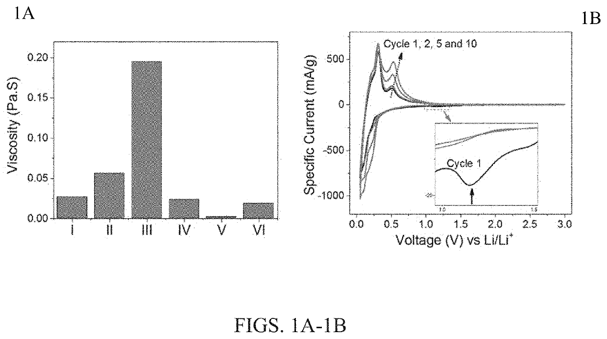
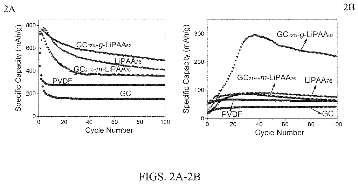
[0010]By virtue of the improved properties of the anodic compositions described herein, the resulting lithium-ion battery containing the anodic composition described above provides several advantages over conventional lithium-ion batteries of the art, including high reversible capacities, high retention of capacity after hundreds or thousands of cycles, and high coulombic efficiencies and retention thereof. Compared with polyvinylidene fluoride (PVDF), glycol chitosan (GC), or a physical mixture of GC and lithium polyacrylate (LiPAA), the novel graft block copolymers described herein provide significantly improved binder performance. As further discussed below, with the same chemical composition and functional group ratio, a representative graft block copolymer (e.g., GC-g-LiPAA) reveals improved cycling performance in both capacity retention (495 mAh / g vs. 356 mAh / g at 100th cycle) and coulombic efficiency (90.3% vs 88.1% at 1st cycle) than the physical mixing of GC and LiPAA. Galvanostatic results also demonstrate the significant impacts of different architecture parameters of graft copolymers on their ultimate binder performance. For example, by simply changing the side chain length of GC-g-LiPAA, the retaining de-lithiation capacity after 100 cycles varies from 347 mAh / g to 495 mAh / g. This invention also demonstrated that the GC-g-LiPAA with longer side-chain length and higher grafting density is preferred as the polymer binder for silicon / graphite composite electrode, which gave higher performance of silicon / graphite electrode than the current-state of the art.
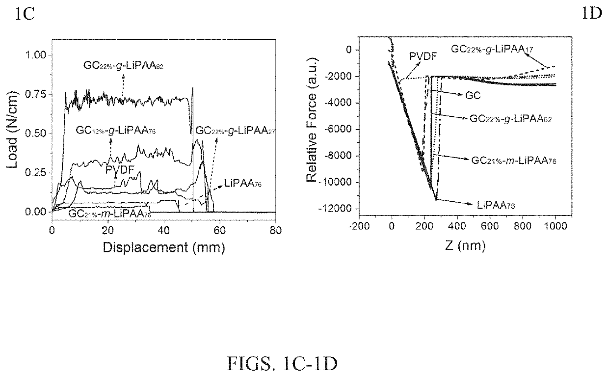
[0011]In particular embodiments, the graft copolymer GC-g-LiPAA with GC as backbone and lithium polyacrylate (LiPAA) as side chains was obtained by RAFT polymerization of acrylic acid (AA) followed by the neutralization of LiOH. The side chain length is also tunable by changing the feed ratio during the reaction, which was confirmed by 1H NMR and IR spectral analysis. By using an environmentally friendly and economically saving solvent, such as water, a high mass-loading silicon / graphite composite electrode (active materials>2.5 mg / cm2) based on graft copolymer (GC-g-LiPAA) was fabricated and tested by galvanostatic measurement. Compared with the linear analogues, such as GC and physical mixing of GC and LiPAA, silicon / graphite composite electrodes made with the graft copolymer GC-g-LiPAA exhibits significantly improved initial discharge capacity, long-term retaining capacity, and coulombic efficiency. With the same chemical composition and functional group ratio, the improved cycling performance of graft block copolymer GC-g-LiPAA in both retaining capacity and coulombic efficiency demonstrated the importance of the polymer binder architecture. These results also demonstrated that the GC-g-LiPAA with longer side-chain length and higher grafting density is preferred as the polymer binder for silicon / graphite composite electrode due to the enhanced interaction with the anode composite, which was supported by the higher peeling strength and increased solution viscosity.

Problems solved by technology

However, the high specific capacity of the silicon-based electrode is typically observed only at the initial cycles, and cannot meet the long cycle life required for typical electric vehicle application.
However, the complex and costly production process make these approaches challenging to deploy in practical applications.

Method used


Image

  • Block graft copolymer binders and their use in silicon-containing anodes of lithium-ion batteries
  • Block graft copolymer binders and their use in silicon-containing anodes of lithium-ion batteries
  • Block graft copolymer binders and their use in silicon-containing anodes of lithium-ion batteries

Examples


examples

[0046]Synthesis of a Series of Graft Polymer Compositions Containing a Glycol Chitosan (GC) Backbone and Poly(Acrylic Acid) (PAA) Graft Polymer Side Chains

[0047]The synthetic methodology used in the following experiments is in accordance with the following general scheme:

[0048]

[0049]Synthesis of the Macro-RAFT-CTA (Compound 3).

[0050]A typical synthesis of GC22%-RAFT was performed as follows: 800 mg (3.60 mmol repeating units) of GC was dissolved in 120 mL of mixed solvent V(H2O) / V(CH3OH)=2:1 by vigorously stirring overnight at 45° C. EDC (0.552 g, 2.88 mmol) and NHS (0.332 g, 2.88 mmol) were added to the solution by the addition of 0.514 g (2.16 mmol) of carboxylic acid terminated RAFT-CTA (compound 2) in 10 mL of mixed solvent V(H2O) / V(CH3OH)=1:1. The mixture was stirred at 35° C. for two days before it was purified by dialysis using a semi-permeable membrane (Mw=3.5 kDa) against the mixed solvent V(H2O) / V(CH3OH)=3:1. The structure of the product was confirmed by 1H NMR and IR spec...


PUM

PropertyMeasurementUnit
coulombic efficiencyaaaaaaaaaa
temperatureaaaaaaaaaa

Abstract

A graft copolymer composition comprising the following structure:wherein: Ax represents a polymer backbone having a number of polymerized monomer units x; [By] represents a multiplicity of a graft polymer side chain having a number of polymerized monomer units y, and at least a portion of the monomer units in By contains a group —C(O)OM, with M independently selected from H and alkali metals; [C] represents a multiplicity of positions on the polymer backbone Ax where the graft polymer side chain B or any other graft polymer side chain is not attached; the subscript w represents a grafting density of the group By, wherein w is an integer within a range of 10-50%; and the subscript z represents a density of the group C, wherein z=(100−w) %. The invention is also directed to lithium-ion batteries in which the above-described composition is incorporated in an anode of the battery.

Description

CROSS REFERENCE TO RELATED APPLICATION[0001]The present application claims benefit of U.S. Provisional Application No. 62 / 619,364, filed on Jan. 19, 2018, all of the contents of which are incorporated herein by reference.GOVERNMENT SUPPORT[0002]This invention was made with government support under Prime Contract No. DE-AC05-00OR22725 awarded by the U.S. Department of Energy. The government has certain rights in the invention.FIELD OF THE INVENTION[0003]The present invention generally relates to anode compositions for lithium-ion batteries, and more particularly, to lithium-ion batteries having a silicon-containing anode.BACKGROUND OF THE INVENTION[0004]Increasing the energy density of the lithium-ion battery (LIB) is necessary to meet the demands for their expanding applications from portable electronics to large-scale emerging applications, such as renewable energy storage grids and electric vehicles that require acceptable driving distance upon a single charging. Among many candid...

Claims


Application Information

Patent Timeline
Patent Type & Authority Patents(United States)
IPC IPC(8): H01M4/62H01M10/0525C08L33/02C08L5/08C08F251/00C08B37/08C08F293/00H01M4/02
CPCH01M4/622C08B37/003C08F251/00C08F293/005C08L5/08C08L33/02H01M10/0525C08F2438/03C08L2203/20H01M2004/027H01M4/362H01M4/133H01M4/134B82Y30/00Y02E60/10C08F220/06
Inventor SAITO, TOMONORICAO, PENGFEINANDA, JAGJITABDELMALAK, MICHAEL NAGUIB
Owner UT BATTELLE LLC
Why Eureka
Try Eureka