Duty-cycle correction circuit for DDR devices

a duty-cycle correction and circuit technology, applied in pulse manipulation, pulse automatic control, pulse technique, etc., can solve the problems of increasing the likelihood of adding jitter to the signal, and less likely to achieve a 50% duty-cycl

Active Publication Date: 2021-05-11
FARADAY TECH CORP
View PDF3 Cites 9 Cited by
  • Summary
  • Abstract
  • Description
  • Claims
  • Application Information

AI Technical Summary

Problems solved by technology

Having more delay stages increases the likelihood of adding jitter to the s

Method used


Image

  • Duty-cycle correction circuit for DDR devices
  • Duty-cycle correction circuit for DDR devices
  • Duty-cycle correction circuit for DDR devices

Examples


Embodiment Construction

[0024]The method and circuit of the present invention aims to improve upon the duty-cycle correction method of the related art.

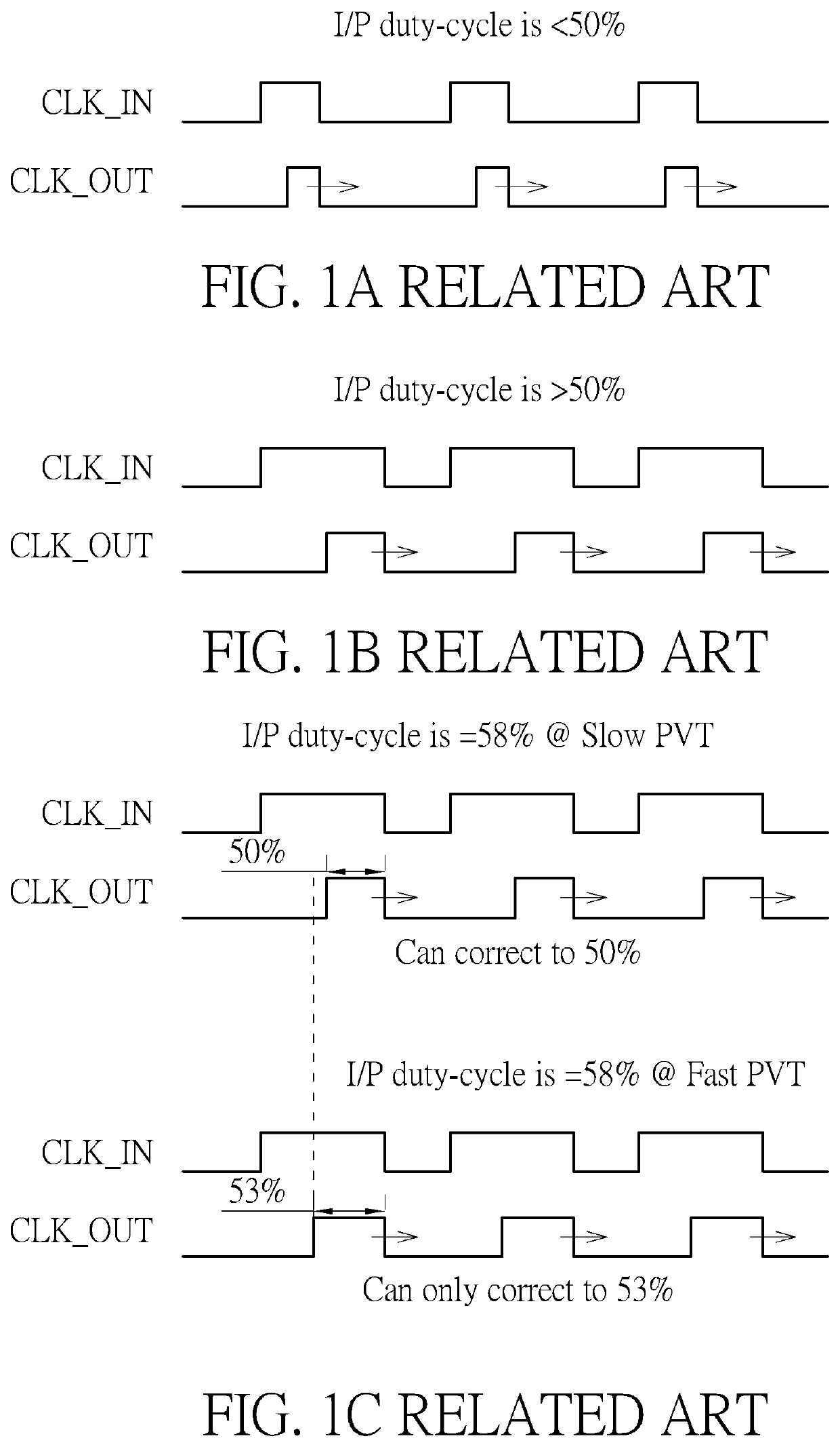
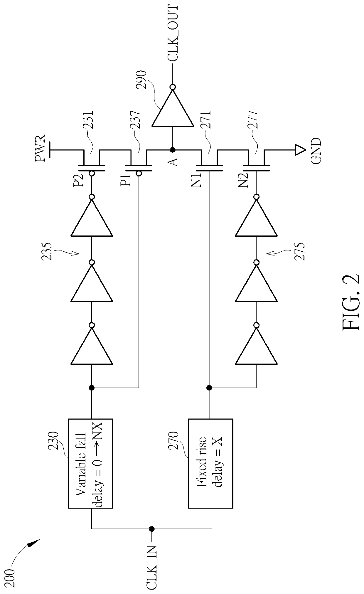
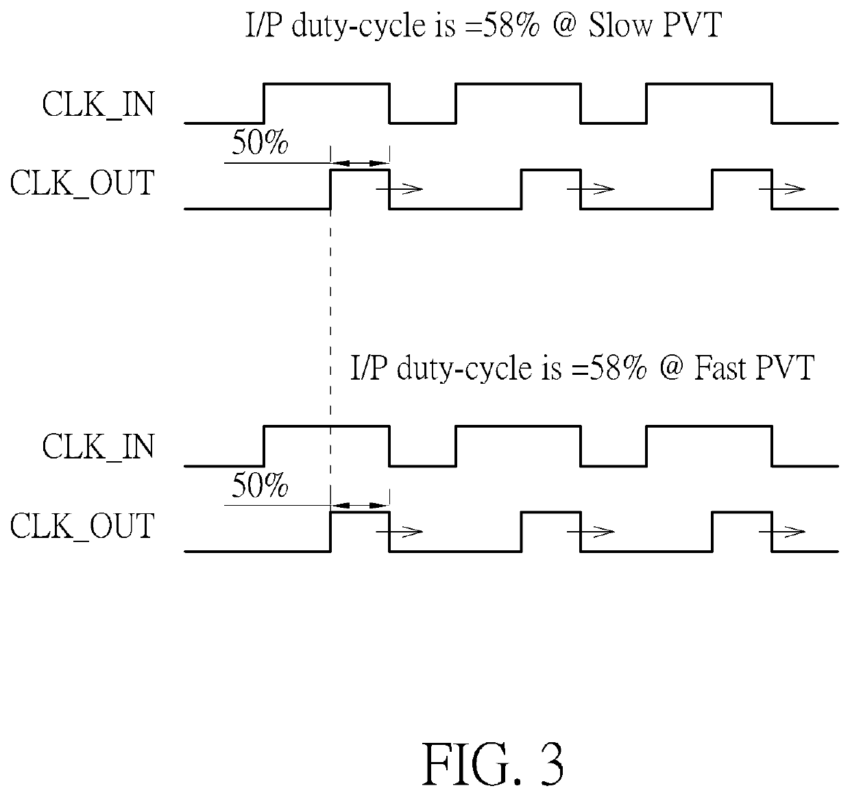
[0025]The present invention takes as its basis the second solution detailed in the background section, where a fixed delay is added to the rising edge of a signal, and the falling edge is shifted by a variable amount. As detailed in the background, the rising edge delay occurs due to PVT variations. The present invention therefore employs a method which can track the rising edge delay with the PVT, and thereby generate a fixed rising edge delay which is constant for a particular chip or wafer (which will have constant PVT) but can be varied for a different chip or wafer with different PVT.

[0026]This is achieved by using a Master Delay Locked Loop (MDLL) code. As is well-known in the art, the MDLL can track changes in PVT to provide a PVT compensated code. The MDLL will calibrate to one clock cycle under any PVT conditions. Once the MDLL code (defined as ‘m’)...


PUM


Abstract

A method for performing duty-cycle correction of an output clock in a Double Data Rate (DDR) system includes: setting a fixed delay of a rising-edge of the output clock as a parameter X which is equal to a digital Master Delay Locked Loop (MDLL) code of the DDR system multiplied by a percentage representing an estimated distortion of the duty-cycle of the output clock from a desired duty-cycle; shifting the rising-edge of the output clock by the fixed delay; and determining whether a duty cycle of the shifted output clock meets the desired duty-cycle. When a duty-cycle of the shifted output clock meets the desired duty-cycle, the fixed rising-edge delay is taken as a final delay code for the output clock; otherwise, a falling-edge of the output clock is shifted by an amount in a range between 0 and NX, wherein N is an integer.

Description

BACKGROUND OF THE INVENTION1. Field of the Invention[0001]The invention is related to duty-cycle correction, and more particularly, to duty-cycle correction which can correct an output duty-cycle to 50% and is constant for all process, voltage and temperature variations.2. Description of the Prior Art[0002]A common aim of duty-cycle correction is to achieve a duty-cycle of 50%, i.e. the portion of a time period for which a signal is positive is the same as the portion of the time period for which the signal is negative. This allows the signal to be used in differential applications.[0003]The related art provides two solutions for duty-cycle correction. In a first solution, when the duty-cycle of a square wave signal is initially less than 50%, the falling edge of the signal can be shifted so that the positive portion of the duty-cycle is extended. When the duty-cycle of a square wave signal is initially greater than 50%, the rising edge of the signal can be shifted so that the posit...

Claims


Application Information

Patent Timeline
IPC IPC(8): H03K5/156H03L7/081
CPCH03K5/1565H03L7/0814H03L7/0818
Inventor SUBRAMANIAN, SIVARAMAKRISHNANCHERUKU, SRIDHARMOHANTA, SANDEEP KUMARSHAIK, HUSSAINVALI
Owner FARADAY TECH CORP
Why Eureka
Try Eureka