Steering system with an actuating device, and use of the steering system with actuating device

a technology of actuating device and steering system, which is applied in the direction of mechanical equipment, transportation and packaging, and transportation, can solve the problems of occupying a lot of space, and achieve the effects of high efficiency, improved volume efficiency, and high torqu

Active Publication Date: 2021-05-18
ZF FRIEDRICHSHAFEN AG
View PDF18 Cites 1 Cited by
  • Summary
  • Abstract
  • Description
  • Claims
  • Application Information

AI Technical Summary

Benefits of technology

[0009]The electric motor (E-motor) is preferably in the form of a brushless vernier electric motor. Such E-motors are highly efficient electric motors which, compared with conventional electric motors, have better volume efficiency. While occupying little volume, a vernier motor can produce a higher torque than a conventional E-motor with a correspondingly larger volume. In other words an E-motor can be made smaller and at the same time have higher power. To put it differently, for the same size as a conventional E-motor a comparatively much higher power can be obtained. Thus, for the actuating device and the steering system, especially a rear axle steering system, a very compact steering system can be produced so that the fitting space required for the steering system, in particular a rear axle steering system, can be significantly reduced.
[0010]The vernier motor is not only smaller than a comparable electric motor. It is also lighter and has greater power efficiency than a comparable conventional E-motor with sufficient torque to drive the spindle drive of a steering system, particularly in a rear axle steering system with a spindle that can move axially relative to a housing. Namely, due to the design the weight of the magnets can be reduced. Consequently smaller amounts of rare earth metals have to be used to make the magnets, and this substantially reduces the cost of a vernier motor compared with a comparable E-motor with the same power.
[0011]In a first embodiment the vernier motor is arranged with its longitudinal axis parallel to the longitudinal axis of the spindle and spindle nut. In this case the spindle nut can be driven by the vernier motor by way of a gear system, preferably by means of a traction drive with drive elements or by means of a gear drive, in particular a planetary gearset. Of particular advantage is the smaller fitting space required by the vernier motor and thus by the actuating device and steering system as a whole when the E-motor is arranged axis-parallel to the housing of the actuating device.
[0012]In a preferred further embodiment the vernier motor is arranged coaxially with the spindle. In contrast to the previously mentioned axis-parallel arrangement, a coaxial structure can provide a still more compact form of the actuating device and steering system. It is true that this principle is already known from conventional hollow-shaft motors in steering systems. However, here too the special vernier motor enables a very substantial reduction of the fitting space. Preferably the vernier motor has a stator rotationally fixed relative to the housing, with a rotor, mounted to rotate inside the stator, coupled to the spindle nut. In this type of E-motor, magnets are arranged outside the stator, but compared with conventional E-motors these are much smaller so that the fitting space occupied by the motor as a whole is reduced. For that reason the outer diameter of the actuating device is also reduced. In this embodiment there is direct coupling to the spindle nut.
[0014]According to another aspect of the invention, it is provided that the steering system and its actuating device are used as the actuator of a rear axle steering system or in a rear axle steering system of a motor vehicle. Due to the lower energy demand of the vernier electric motor resulting from its already mentioned higher power density, less energy is drawn from the on-board electrical system of the motor vehicle for adjusting the rear wheels than when an actuating device with a conventional electric motor is used. The smaller energy uptake during such an adjustment also results in less operating noise when using the actuator. Furthermore, the weight reduction has economical consequences for vehicles with rear axle steering.

Problems solved by technology

This spiral drive is arranged at the end of a steering gear system, whereby the steering has a large axial extension and therefore takes up a lot of space.

Method used


Image

  • Steering system with an actuating device, and use of the steering system with actuating device
  • Steering system with an actuating device, and use of the steering system with actuating device

Examples


Embodiment Construction

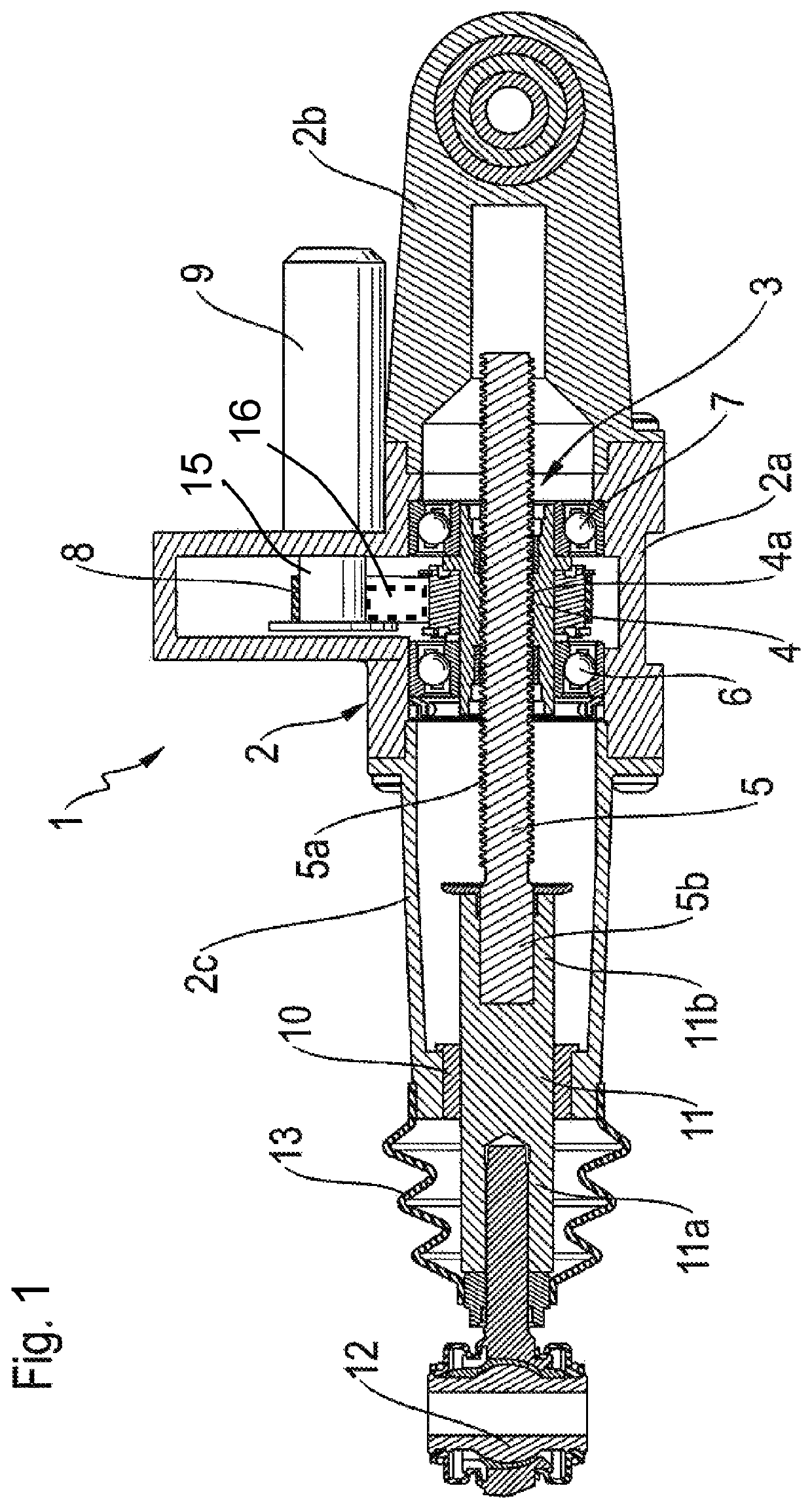
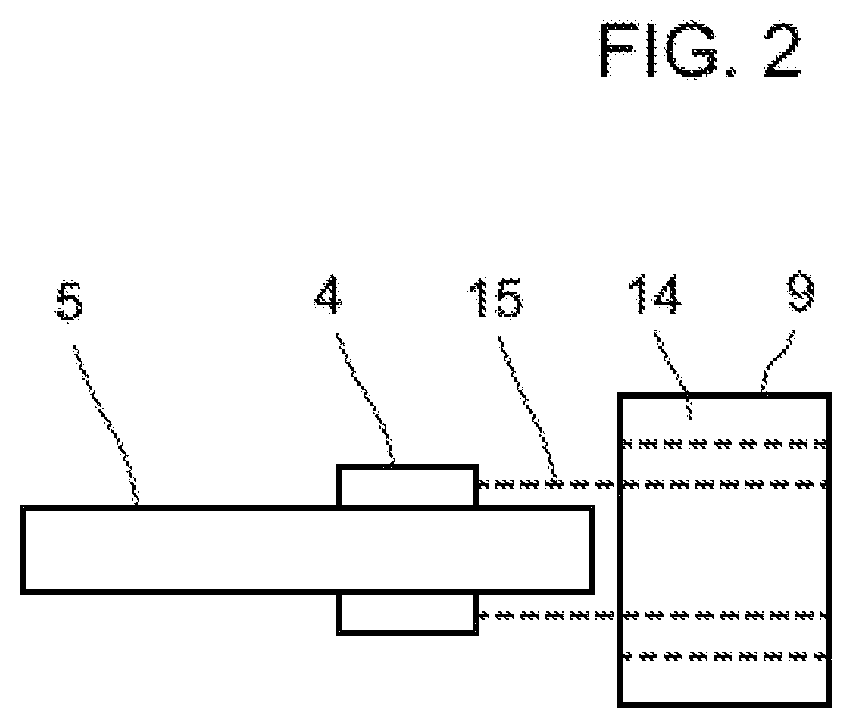
[0019]FIG. 1 shows a longitudinal section of the structure of a simple electric actuator 1 (also referred to as an actuating device), i.e. one that acts on only one wheel, for a rear axle steering system of a motor vehicle. The actuator 1 has a multi-component housing 2 in which is arranged a spindle drive 3 comprising a spindle nut 4 and a spindle 5 that engages with the spindle nut 4 and can be displaced axially. The spindle 5 has a spindle thread or outer thread 5a and the nut has a nut thread or inner thread 4a, which are in the form of a movement thread, preferably a trapezoid thread. The spindle nut 4, which is supported rotatably in the housing 2 by two roller bearings 6 and 7, is driven via a belt drive 8 by an electric motor 9. As an alternative, the electric motor 9 has a rotor 15 which indirectly drives the spindle nut 4 by means of interposed gearing 16 in the form of a drive gear and which is diagrammatically shown with dashed lines in FIG. 1. The housing 2 comprises th...


PUM


Abstract

A steering system with an actuating device (1), in particular a rear axle steering system, having a spindle drive (3) with a spindle (5) and a spindle nut (4) which is fitted into the housing (2) of the steering system in a positionally fixed but rotatable manner and is driven by an electric motor (9). The electric motor (9) is a vernier motor that drives the spindle drive (3) and is integrated in the spindle drive (3). The actuating device (1) is used for a rear axle steering system of a motor vehicle.

Description

[0001]This application is a National Stage completion of PCT / EP2017 / 060006 filed Apr. 27, 2017, which claims priority from German patent application serial no. 10 2017 205 666.5 filed Apr. 4, 2017 and German patent application serial no. 10 2016 209 160.3 filed May 25, 2016.FIELD OF THE INVENTION[0002]The invention relates to a steering system with an actuating device, which comprises a spindle with a spindle thread and a spindle nut with a nut thread that engages with the spindle thread. The invention also relates to the use of the actuating device.BACKGROUND OF THE INVENTION[0003]Steering systems with actuating devices having a threaded spindle for axial displacement are known in a variety of designs. In a first version according to JP 2002079947 A2 for steering the wheels on a front axle, a so-termed vernier motor is used, which by virtue of a special structure and the control of numerous coils produces a high torque while occupying little fitting space. This spiral drive is arra...

Claims


Application Information

Patent Timeline
Patent Type & Authority Patents(United States)
IPC IPC(8): B62D5/04B62D7/14B62D3/06B62D7/06F16H25/20
CPCB62D5/0445B62D3/06B62D5/0424B62D7/146B62D7/06F16H25/20F16H2025/2096
Inventor KLANK, MICHAELVORTMEYER, JENSPFISTERER, HANS-JÜRGENRIECHMANN, ADRIANANNEKEN, CHRISTOPH
Owner ZF FRIEDRICHSHAFEN AG
Why Eureka
Try Eureka