Energy supply

a technology for energy supply and electrical energy, applied in the direction of generator/motor, basic electric elements, solid-state devices, etc., can solve the problems of limited use range, limited variant described in this document, and limited use range of systems known from the prior art, etc., to achieve easy manufacturing and fit, and the effect of low cos

Active Publication Date: 2021-05-25
WITTENSTEIN SE
View PDF9 Cites 0 Cited by
  • Summary
  • Abstract
  • Description
  • Claims
  • Application Information

AI Technical Summary

Benefits of technology

[0012]In typical embodiments, the Peltier element is at least partially bordered by the layer of insulation, which is typically in the form of an insulating plate. This provides a particularly compact design.
[0014]In embodiments, the Peltier element is arranged between an adapter plate and a motor or a gear mechanism. The arrangement between such component parts provides the possibility of using a reliably occurring heat flow directly. Adapter plates are generally used in order to connect motors to gear mechanisms, for example in order to provide a possibility of using different motors with one type of gear mechanism construction.
[0028]The solution with a plastic plate as layer of insulation provides the advantage in comparison with other solutions that it is easy to manufacture and fit. As a result, the total construction is inexpensive. In comparison with the solution using spacer sleeves and air as insulation, the interior of the adapter plate is sealed off from the exterior if the layer of insulation at least partially or completely borders the Peltier element. Therefore, it is not possible for any contamination to enter the interior of the adapter plate.

Problems solved by technology

However, the systems known from the prior art sometimes do not have a very wide variety of usage or have only a low power or require additional cooling elements and therefore additional installation space for producing a sufficient temperature drop.
However, the variant described in this document is restricted in respect of the variability of use.

Method used


Image

  • Energy supply
  • Energy supply
  • Energy supply

Examples


Embodiment Construction

[0035]Typical exemplary embodiments will be described below, wherein sometimes the same reference symbols are used for identical or similar parts, sometimes even for a plurality of different embodiments. In principle, the application is not restricted to the different embodiments, but rather the scope is defined by the claims. Sometimes, individual parts are explained purely in connection with one figure and if these parts are illustrated in further figures they are not necessarily described once again.

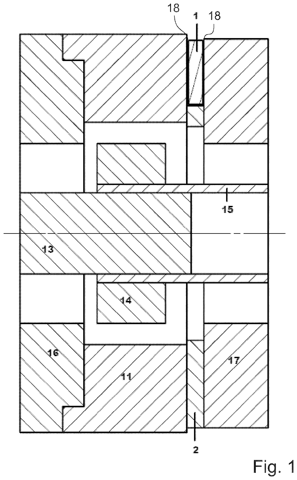
[0036]FIG. 1 shows an exemplary embodiment of a typical embodiment of the invention in a cross-sectional view. The embodiment shown in FIG. 1 comprises a gear mechanism 17 (for example SP100 gear mechanism by WITTENSTEIN SE). A 3.7 mm-thick layer of insulation 2 consisting of Bakelite (plate PF 1110) with the same outer diameter as the drive flange of the gear mechanism 17 has been installed between an adapter plate 11 and the drive flange of the gear mechanism 17.

[0037]The layer of i...


PUM


Abstract

Apparatus for providing electrical energy, in particular for providing electrical energy from a heat flow originating from an electric motor, including a first component part, a second component part, wherein a Peltier element is arranged between the first component part and the second component part, said Peltier element being at least partially surrounded by a layer of insulation provided between the first component part and the second component part, with the result that the Peltier element forms a thermal bridge between the first and the second component parts, and wherein the first and the second component parts are selected from the following group: gear mechanism, motor and adapter plate.

Description

FIELD OF THE INVENTION[0001]The invention relates to an apparatus for providing electrical energy and to a thereof.PRIOR ART[0002]Systems which utilize a temperature difference between a component part which heats up during operation and the surrounding environment to provide electrical energy for consumers are known from the prior art. Such energy production can take place by means of Peltier elements.[0003]The energy produced in this way is typically used for applications close to the component part which heats up, for example a motor.[0004]However, the systems known from the prior art sometimes do not have a very wide variety of usage or have only a low power or require additional cooling elements and therefore additional installation space for producing a sufficient temperature drop.[0005]WO 2015 / 128050 A discloses a possibility of supplying power to an electronic circuit from a Peltier element. However, the variant described in this document is restricted in respect of the vari...

Claims


Application Information

Patent Timeline
Patent Type & Authority Patents(United States)
IPC IPC(8): H01L23/38H01L35/32H01L33/64
CPCH01L23/38H01L33/645H01L35/32H02N11/002H10N10/17
Inventor SCHUSTER, JÜRGENHOFFMANN, ROLF
Owner WITTENSTEIN SE
Why Eureka
Try Eureka