Switched suction jet pump

a suction jet and switch technology, applied in the direction of non-positive displacement pumps, machines/engines, engine components, etc., can solve the problems of throttling of the propellant mass flow, and achieve the effect of reducing the nozzle cross-section and being very compactly constructed

Active Publication Date: 2021-06-01
POLYTEC PLASTICS GERMANY
View PDF22 Cites 0 Cited by
  • Summary
  • Abstract
  • Description
  • Claims
  • Application Information

AI Technical Summary

Benefits of technology

[0008]The intention is not thereby to throttle the pressure for operating the suction jet pump as in DE 10 2013 000236 A1, but to reduce the nozzle cross-section of the jet nozzle directly. This has the advantage that the complete boost pr...

Problems solved by technology

Nevertheless, throttling of t...

Method used


Image

  • Switched suction jet pump
  • Switched suction jet pump

Examples


Embodiment Construction

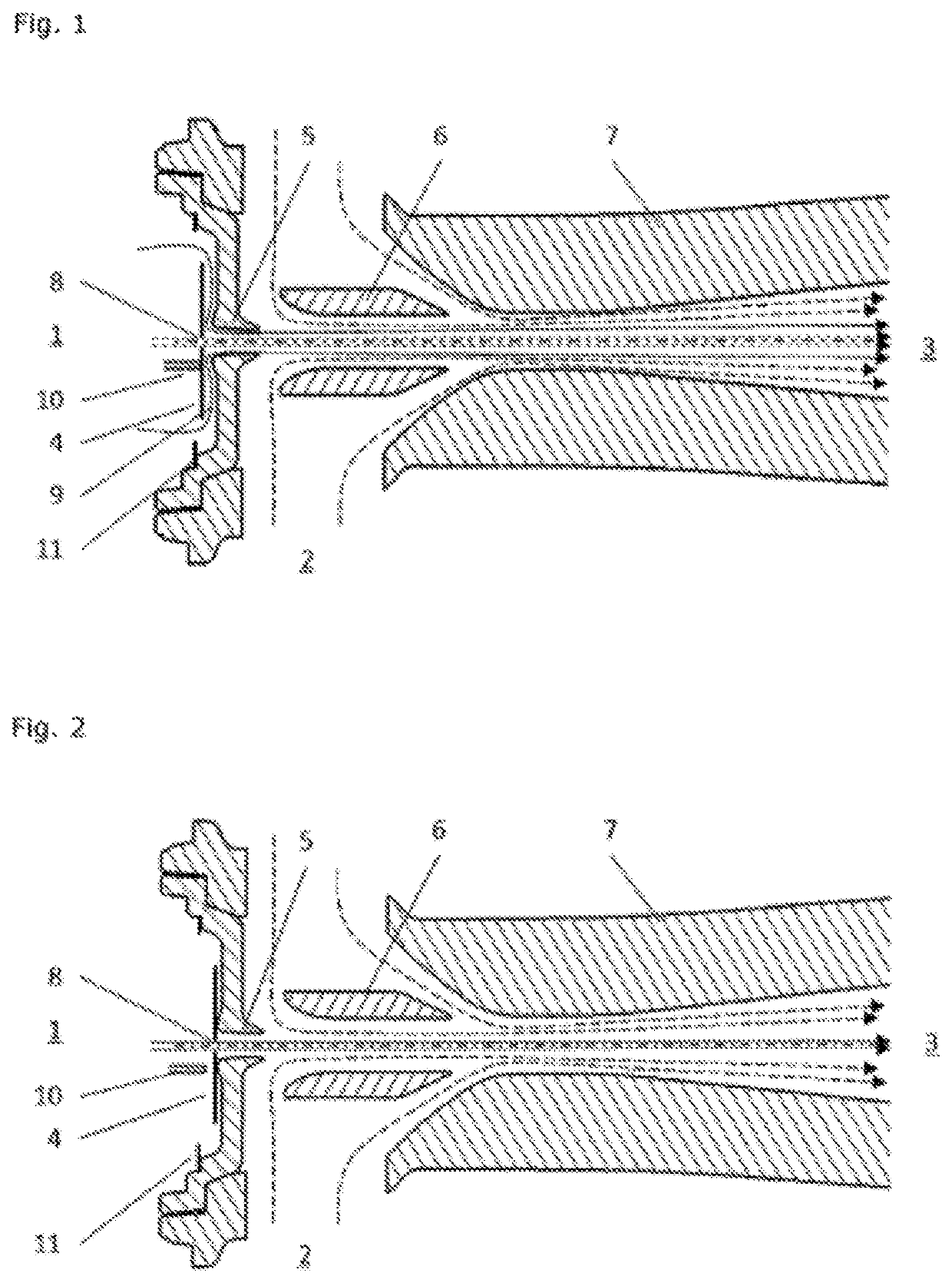
[0013]In particular, the invention consists of a single-stage or multistage suction jet pump as shown in FIGS. 1 and 2, comprising a jet nozzle 5, a diffuser 7, and optionally further nozzles 6. Upstream from the jet nozzle 5, there is the overpressure zone 1, which may be the boost pressure of a turbo engine, for example. The overpressure accelerates the jet fluid through the jet nozzle 5, so that the maximum speed is observed behind the nozzle. The dynamic pressure is thereby increased in this zone. For reasons of energy preservation, the static pressure drops. Air is thereby sucked from the suction zone 2 and then flows with the jet air through the diffuser 7, where the flow is decelerated. This can be utilized, for example, to produce a negative pressure in a crankcase or in a tank. The overall flow 3 can then be returned to the intake air of the internal combustion engine (for example, upstream from the compressor).

[0014]According to the invention, it is particularly preferred ...


PUM


Abstract

The invention relates to a single-stage or multistage suction jet pump comprising a propelling nozzle (5), one or more suction nozzles (2), a diffuser (7), and a volume flow limiting valve in or directly in front of the propelling nozzle. The volume flow limiting valve has a valve element (4) in the overpressure region (1) of the suction jet pump, said valve element having an opening (8) with a cross-sectional area which is smaller than the cross-sectional area of the propelling nozzle (5). The valve element spans at least one additional gap opening (9) which first releases the cross-section of the gap opening (9) when the pressure difference between the overpressure region (1) and the suction region (2) increases and which switches in the event of a defined large pressure drop and the valve element (4) reduces or closes the cross-section of the gap opening (9) such that the volume flow flowing over the opening (8) is limited to a defined level even in the event of a further increasing pressure difference.

Description

FIELD OF THE INVENTION[0001]The invention relates to a switched single-stage or multistage suction jet pump, comprising a jet nozzle, one or more suction nozzles, a diffuser, and a volume flow limiting valve.BACKGROUND OF THE INVENTION[0002]The suction performance of a usual suction jet pump is controlled through the pressure acting on the jet nozzle. In an internal combustion engine with turbo charging, this propellant pressure is branched off the boost pressure of the engine and depends on the respective engine load point. The higher the torque produced, the higher is the boost pressure. If a suction jet pump is employed to produce a negative pressure in the crankcase or for tank ventilation, a sufficient suction performance is required already for lower boost pressures. However, the suction performance of the suction jet pump usually need not increase in parallel with the increasing boost pressure. For this reason, it is reasonable that the suction jet pump is throttled from a de...

Claims


Application Information

Patent Timeline
IPC IPC(8): F04F5/54F04F5/46F04F5/22F01M13/02F01M13/04
CPCF04F5/461F04F5/22F01M13/022F01M13/04F01M2013/026F04F5/466F04F5/00
Inventor BERDING, CHRISTIANLESON, CHRISTOPH
Owner POLYTEC PLASTICS GERMANY
Why Eureka
Try Eureka