
Simultaneous measurement of range and velocity using optical radar

a radar and optical technology, applied in the field of traditional light detection and ranging, can solve the problems of not being able to measure the range and velocity of objects simultaneously, unable to achieve the effect of achieving the effect of reducing the power output of the system

Active Publication Date: 2021-06-01
AEVA INC
View PDF3 Cites 2 Cited by
  • Summary
  • Abstract
  • Description
  • Claims
  • Application Information

AI Technical Summary

Benefits of technology

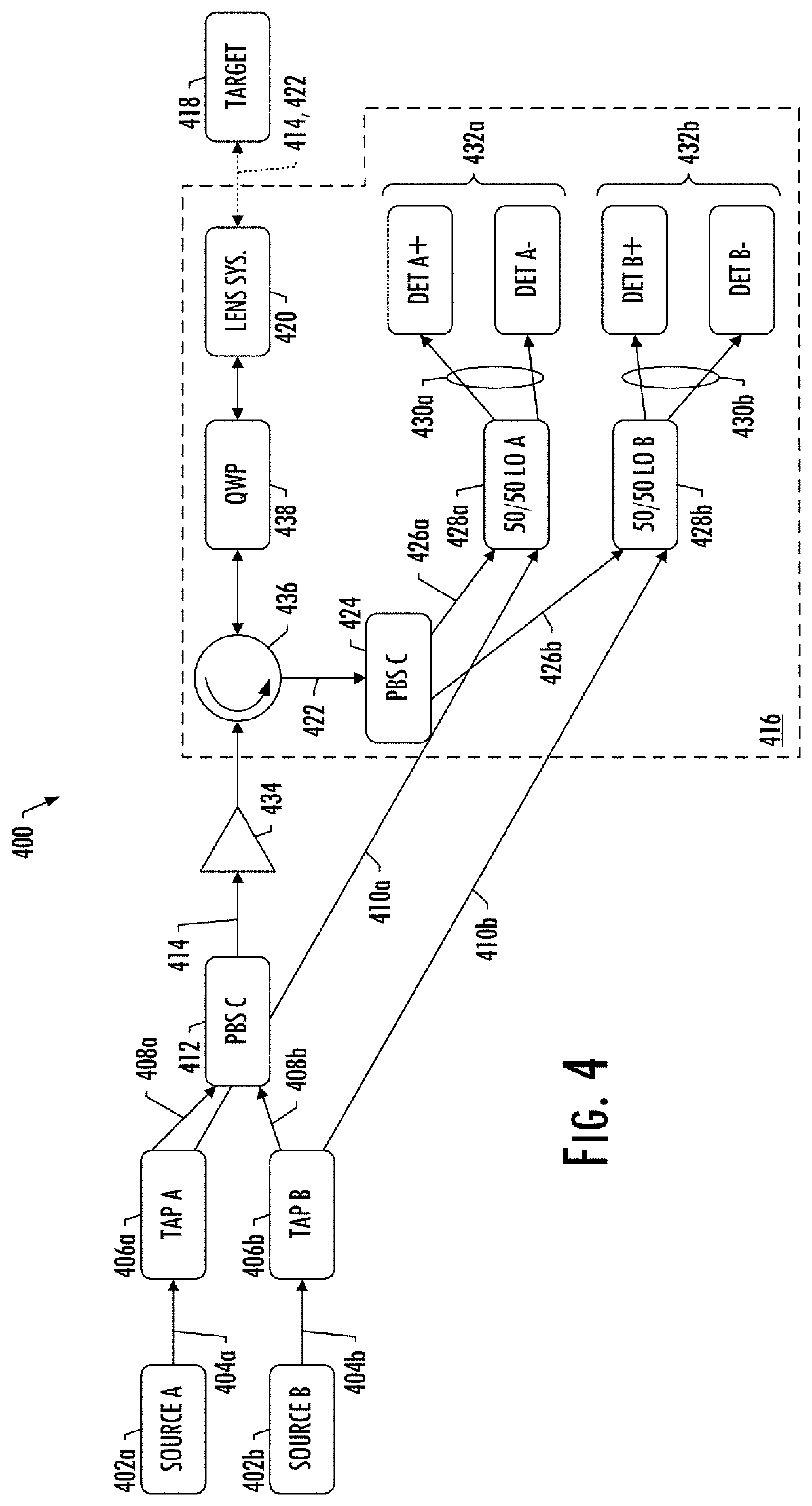
The present disclosure provides a light detection and ranging (LiDAR) system that includes a first optical source and a second optical source that emit opposite polarization optical beams. The system also includes a first tap and a second tap to split the optical beams, a first optical splitter to split a low-power path optical beam into multiple low-power path optical beams, a second polarization beam splitter to split the low-power path optical beams, and multiple optical arrangements for multiple targets. The system can detect and range targets using the high-power and low-power path optical beams. The technical effects of the system include improved detection and ranging of targets with high accuracy and efficiency.

Problems solved by technology

Typical LiDAR systems are pulsed based (or direct detection) and they simply cannot measure the range and velocity of the object simultaneously.
Typical FM LiDAR systems are bulky and large and suffer from significant losses in the receive path.
This leads into more power output which is limited by eye safety or shorter ranges.

Method used


Image

  • Simultaneous measurement of range and velocity using optical radar
  • Simultaneous measurement of range and velocity using optical radar
  • Simultaneous measurement of range and velocity using optical radar

Examples


Embodiment Construction

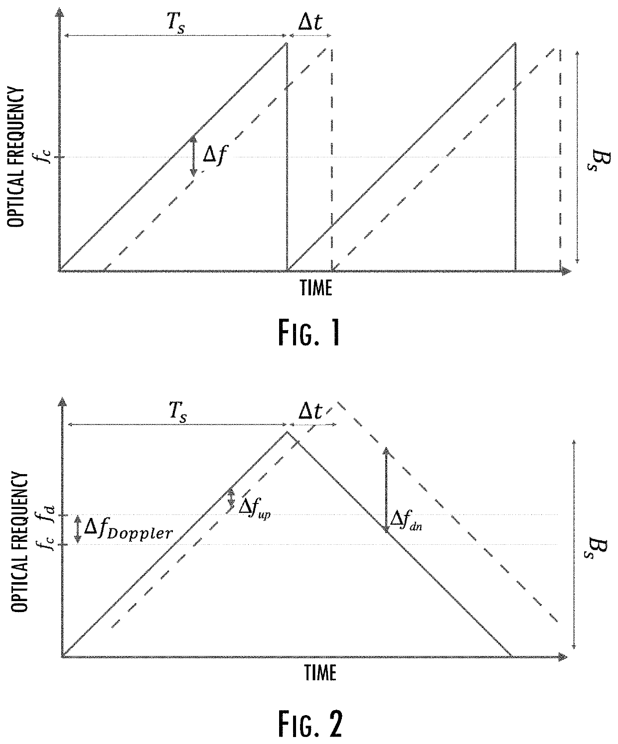
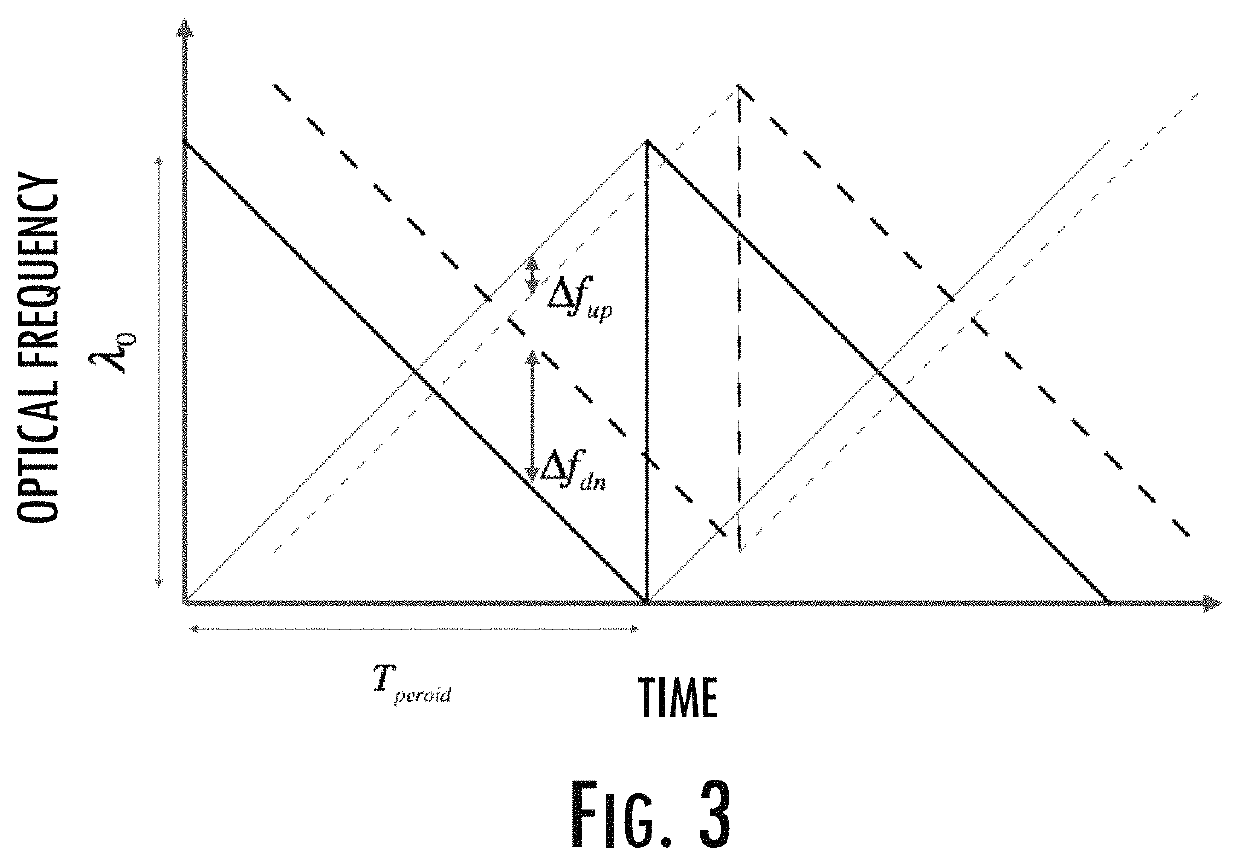
[0036]Example implementations of the present disclosure propose a method to measure the range and velocity simultaneously without suffering major losses in the receive path and with a circuit that is compatible with current photonic integrated circuits such as, but not limited to, silicon photonics, silica or programmable logic controller (PLC) processes.

[0037]Example implementations of the present disclosure are directed to a method to construct an optical radar that is capable of simultaneous measurement for range and velocity measurement in a compact, mass-manufacturable fashion. Example implementations have application in a number of different contexts, including in sensing contexts such as those in transportation, manufacturing, metrology, medical, security, and the like. For example, in the automotive industry, such a device can assist with spatial awareness for automated driver assist systems, or self-driving vehicles. Additionally, it can help with velocity calibration of a ...


PUM


Abstract

A light detection and ranging system includes optical sources configured to emit respectively first and second optical beams that have opposite polarizations. Taps split the first and second optical beams into first and second high-power path and low-power path optical beams. A first polarization beam splitter combines the first and second high-power path optical beams into a single spatial mode optical beam, which lensing optics launches toward the target, and collects light incident upon the target into a return path. A second polarization beam splitter splits the return optical beam into first and second spatial mode optical beams. Mixers mix the first and second spatial mode optical beams with respectively the first and second low-power path optical beams to produce optical beams first and second beat frequencies, which optical detectors detect and from which range and velocity of the target are determinable.

Description

CROSS-REFERENCE TO RELATED APPLICATION(S)[0001]The present application priority to U.S. Provisional Patent Application No. 62 / 643,414, entitled: Simultaneous Measurement of Range and Velocity using Optical Radar, filed Mar. 15, 2018, the content of which is incorporated herein by reference in its entirety.TECHNOLOGICAL FIELD[0002]The present disclosure relates generally to traditional light detection and ranging (LiDAR) and, in particular, to LiDAR that provides simultaneous measurement of range and velocity across two dimensions.BACKGROUND[0003]Typical LiDAR systems are pulsed based (or direct detection) and they simply cannot measure the range and velocity of the object simultaneously. Example implementations of the present disclosure are based on a different kind of LiDAR system which is frequency modulated (FM). Typical FM LiDAR systems are bulky and large and suffer from significant losses in the receive path. This leads into more power output which is limited by eye safety or ...

Claims


Application Information

Patent Timeline
Patent Type & Authority Patents(United States)
IPC IPC(8): G01C3/08G01S7/499G01S17/58G02B27/28G01S17/26
CPCG01S7/499G01S17/26G01S17/58G02B27/283G01S17/34G01S7/4815
Inventor REZK, MINA
Owner AEVA INC
Learn More