Vehicle front portion structure

a technology for front portions and vehicles, applied in the direction of superstructure connections, roofs, transportation and packaging, etc., can solve the problems of small strain amount before breakage, inability to extend, and possible breakage of connecting members

Active Publication Date: 2021-06-08
TOYOTA JIDOSHA KK
View PDF37 Cites 2 Cited by
  • Summary
  • Abstract
  • Description
  • Claims
  • Application Information

AI Technical Summary

Benefits of technology

[0005]In consideration of the circumstances described above, an object of the present disclosure is to provide a vehicle front portion structure that may suppress breakage of a connecting member and transmit an impact load transmitted from a front side member to a dash cross-member and a rocker.
[0009]Generally speaking, fabrication methods using aluminium alloys include extrusion molding, press working, die-casting, and so forth. A member formed by extrusion molding or press working is referred to as a wrought member, and a member formed by die-casting referred to as a cast member. The use of a cast member for the connecting member can be expected with a view to high flexibility of shaping, ease of joining to other members, and so forth. However, with a cast member, due to the effect of blowholes formed during casting, extension is not allowed when a tension load is applied and a strain amount before breakage is small. In other words, the tensile strength is low. Therefore, a cast member has a low withstand load with respect to tensile loads.
[0026]The vehicle front portion structure according to the present disclosure provides excellent effects in that breakage of the connecting member may be suppressed and an impact load transmitted from the front side member may be transmitted to the dash cross-member, the rocker and the like.

Problems solved by technology

Therefore, when an impact load is applied to the front side member, if a load in a tension direction acts on the connecting member formed of a cast member, the connecting member may break.
However, with a cast member, due to the effect of blowholes formed during casting, extension is not allowed when a tension load is applied and a strain amount before breakage is small.
Therefore, a cast member has a low withstand load with respect to tensile loads.
In this structure, if the welded portion detaches (breaks) while a tensile load is acting on the connecting member, the connecting member may be unable to transmit an impact load to other members.

Method used


Image

  • Vehicle front portion structure
  • Vehicle front portion structure
  • Vehicle front portion structure

Examples


Embodiment Construction

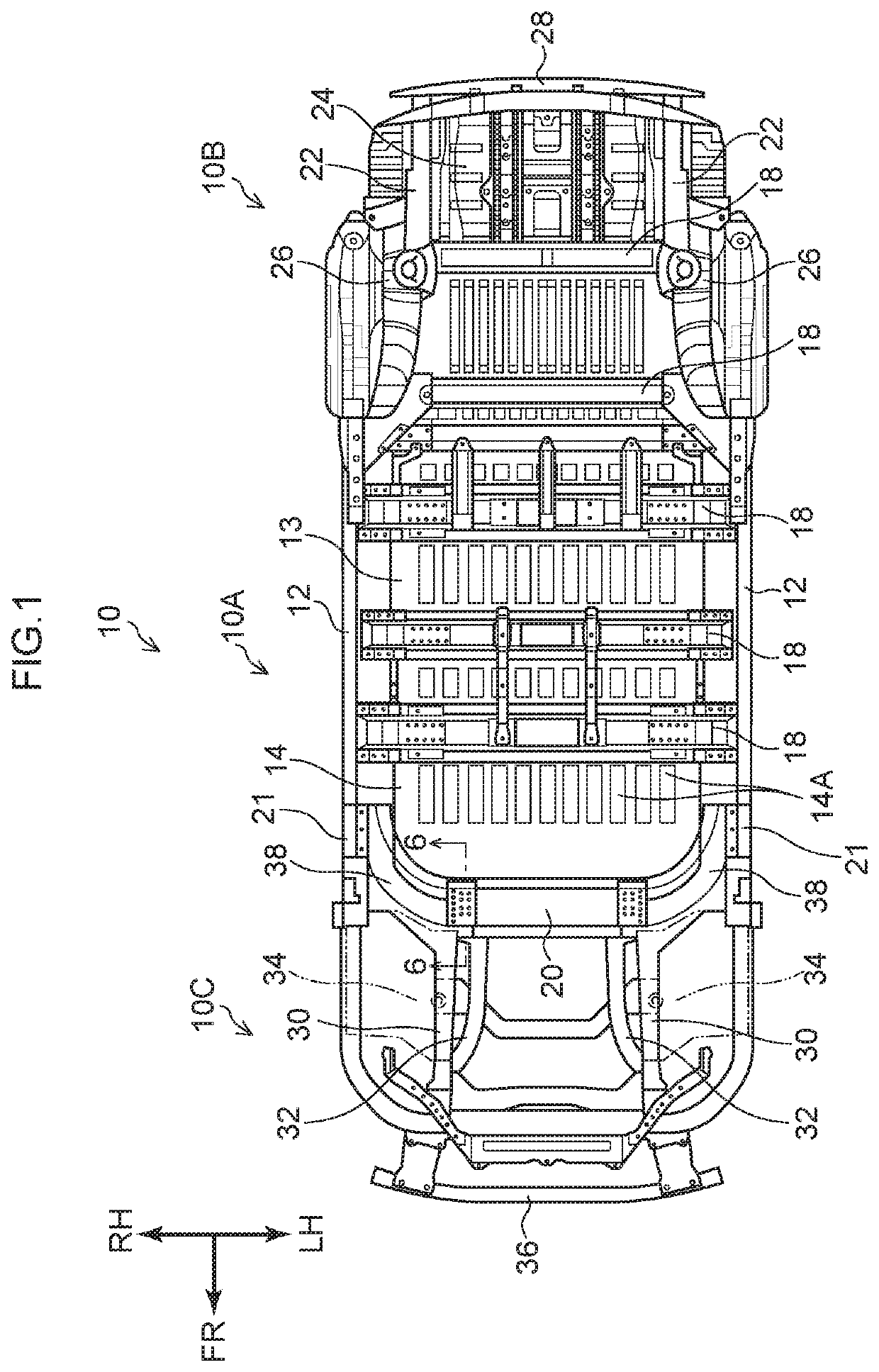
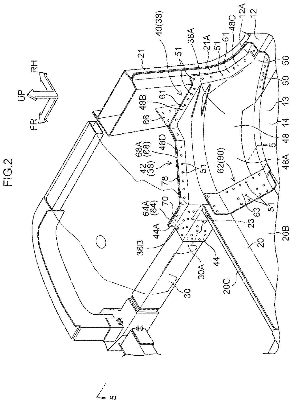
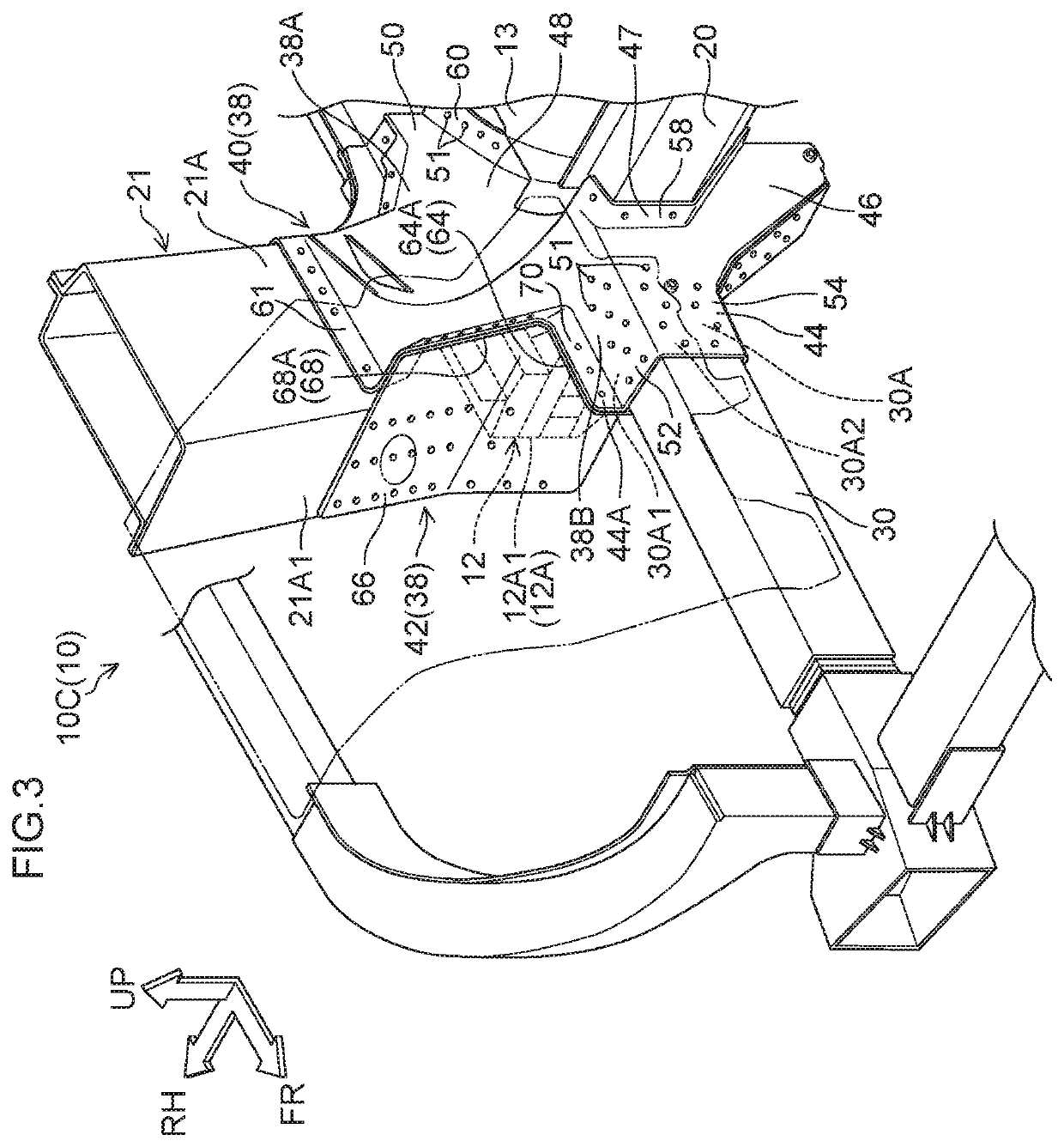
[0041]Below, a vehicle front portion structure according to an exemplary embodiment of the present disclosure is described using the attached drawings. Herein, the arrow FR that is shown where appropriate in the drawings indicates a vehicle front-and-rear direction front side, the arrow UP indicates a vehicle vertical direction upper side, an arrow RH indicates a vehicle width direction right side, and an arrow LH indicates the vehicle width direction left side. Hereinafter, where descriptions are given simply using the directions front and rear, left and right, and upper and lower, unless specifically stated otherwise, these indicate front and rear in the vehicle front-and-rear direction, left and right in the vehicle left-and-right direction (the vehicle width direction), and upper and lower in the vehicle vertical direction.

[0042]—Structures of the Vehicle Front Portion Structure—

[0043]First, structures of the vehicle front portion structure according to the present exemplary emb...


PUM

PropertyMeasurementUnit
widthaaaaaaaaaa
tensileaaaaaaaaaa
compressiveaaaaaaaaaa

Abstract

A reinforcing plate is provided between an inner central portion that structures a portion of a connecting member and a rear end portion of a dash cross-member. The reinforcing plate is a wrought member and is joined (at a join portion) to both the inner central portion and a rear wall portion of the dash cross-member via joining members. Because the wrought member has high tensile strength, when the reinforcing plate is provided at the join portion of the connecting member, a tensile load acting on the join portion may be borne by the reinforcing plate, and breakage of the connecting member may be suppressed. Therefore, an impact load transmitted from a front side member through the connecting member may be transmitted to the dash cross-member and rockers.

Description

CROSS-REFERENCE TO RELATED APPLICATION[0001]This application is based on and claims priority under 35 USC 119 from Japanese Patent Application No. 2018-148811 filed on Aug. 7, 2018, the disclosure of which is incorporated by reference herein.BACKGROUNDTechnical Field[0002]The present disclosure relates to a vehicle front portion structure.Related Art[0003]Japanese Patent Application Laid-Open (JP-A) No. 2001-225766 (Patent Document 1) discloses a technology in which a reinforcing member is provided between a dash cross-member and a floor panel. In this related art, an impact load that is applied to the dash cross-member from a front side member is transmitted through the reinforcing member to a floor tunnel, a side sill (below referred to as a rocker) and the like.[0004]Technologies in which a front side member, dash cross-member and rocker are linked by a connecting member fabricated by die-casting have been considered. Typically, a member fabricated by die-casting (below referred ...

Claims


Application Information

Patent Timeline
Patent Type & Authority Patents(United States)
IPC IPC(8): B60J7/00B62D21/15B21C23/00B62D25/02B62D25/14B62D29/00
CPCB62D21/152B21C23/002B62D25/025B62D25/145B62D29/008B62D25/08B62D25/14B62D25/082B62D25/04B62D27/023
Inventor AYUKAWA, TATSUYA
Owner TOYOTA JIDOSHA KK
Why Eureka
Try Eureka