Valve device for a turbocharger

a valve device and turbocharger technology, which is applied in the direction of springs/dampers, combustion engines, belleville-type springs, etc., can solve the problems of clattering and rattling noises, and the installation space of the spring element in the wastegate valve region of the turbocharger is usually strictly limited

Active Publication Date: 2021-06-29
ELRINGKLINGER AG
View PDF8 Cites 1 Cited by
  • Summary
  • Abstract
  • Description
  • Claims
  • Application Information

AI Technical Summary

Benefits of technology

[0011]The present invention also relates to a spring element for a wastegate valve of a turbocharger as has been defined in the introduction for a valve device, and the spring element according to the invention likewise is characterized in that its rigidity with respect to pressing forces oriented in the direction of the spring element axis is not constant everywhere, but instead is different in the manner as defined above.
[0012]The valve device according to the invention is advantageously configured such that the spring element is held on the valve element shaft at least substantially non-rotatably relative to the valve element carrier, and such that, when the annular transition region has at least substantially the same height everywhere (measured in the direction of the axis of the spring element opening), this transition region has at least one first longitudinal portion, in which the transition region has its greatest width (compared to longitudinal portions other than the at least one first longitudinal portion). If the spring element is then held in the valve device such that, when the valve element is in its closed position, a first longitudinal portion of the spring element transition region as defined above is opposite (in the longitudinal direction of the shaft of the valve element in its closed position) the region of the valve seat against which the valve element sealing surface is initially placed by means of a first sealing surface region as the valve element approaches its closed position, a minimal application of force is required for the adaptation of the valve element to the valve seat. The above-mentioned first longitudinal portion of the spring element transition region is then also opposite the aforementioned first region of the valve element sealing surface.
[0013]Where reference is made above to the fact that (when the valve element is in its closed position) a first longitudinal portion (of greatest width) of the spring element transition region is opposite the first sealing surface region of the valve element sealing surface initially placed against the valve seat, this is not intended to rule out a situation in which the first sealing surface region of the valve element sealing surface is offset relative to the first longitudinal portion of the spring element transition region (transversely to the axis of the valve element shaft).
[0014]Preferred embodiments of the valve device according to the invention are consequently characterized in that the pivot angle plane defined by the pivot movement of the valve element extends through a first, above-defined longitudinal portion of the spring element transition region, which in particular is arranged at least substantially symmetrically with respect to said plane.
[0010]Proceeding from a valve device of the kind defined in the introduction, it is proposed in accordance with the invention, in order to solve the stated problem, to form the spring element such that its rigidity with respect to pressing forces oriented in the axial direction of the spring element is not constant everywhere, but instead is different, in such a way that the valve element sealing surface, when the valve element is pivoted into its closed position, is adaptable to the valve seat with a minimal application of force, with the valve element nevertheless being protected over a maximum operating time at least against appreciable vibration-like movements.
[0014]Preferred embodiments of the valve device according to the invention are consequently characterized in that the pivot angle plane defined by the pivot movement of the valve element extends through a first, above-defined longitudinal portion of the spring element transition region, which in particular is arranged at least substantially symmetrically with respect to said plane.
[0003]During operation of a valve device of this kind, the valve element is moved from its open position to its closed position and vice versa by rotation of the spindle, and in so doing the valve element sealing surface is pivoted (tilted) about the spindle longitudinal axis, more specifically through a pivot angle range, the limits of which are determined by the open and closed positions of the valve element (here, the pivot angle range defines a pivot angle plane which extends perpendicularly to the spindle longitudinal axis and to the plane of the valve element sealing surface and in which the longitudinal axis of the valve element shaft lies). With respect to the axis of its opening and as considered in the direction of this axis, the spring element has a radially outer ring region and a radially inner ring region (adjoining the spring element opening) and also an annular transition region therebetween, such that the radially outer ring region is offset relative to the radially inner ring region in the direction of the axis of the spring element opening, whereby it is made possible to at least mostly eliminate play between the valve element and the valve element carrier (in the longitudinal direction of the valve element shaft) by the spring element.
[0018]Due to the usually confined installation conditions of a turbocharger for the spring element, the spring element advantageously has a half bead, the flank of which is formed by the spring element transition region—in a cross-section through the spring element, the half bead has two bead feet, which are connected to one another by what is known as the flank of the bead. It should be noted at this juncture that in a plan view of the annular spring element a half bead requires less space than what is known as a full bead (measured in a radial direction with respect to the axis of the spring element opening).
[0019]As already mentioned, the present invention also relates to a spring element for a wastegate valve of a turbocharger, more specifically a spring element of this kind formed substantially in a plate-like manner, as has been defined in the introduction for a valve device that is to be improved by the invention.

Problems solved by technology

As will also be presented hereinafter, the forces exerted by the installed spring element onto the valve element during turbocharger operation must not be too great, because, in certain angular positions of the valve element, said valve element can be excited by the exhaust-gas flow to perform vibration-like movements, which during turbocharger operation lead to clattering and rattling noises, which are disadvantageous not only on account of the noise, but also on account of the wear caused by the rattling.
However, the installation space available for the spring element in the region of the wastegate valve in a turbocharger is usually strictly limited, more specifically both in the axial and radial direction of the spring element.

Method used


Image

  • Valve device for a turbocharger
  • Valve device for a turbocharger
  • Valve device for a turbocharger

Examples


Embodiment Construction

[0034]FIGS. 1 to 6 and 6A are largely identical to FIGS. 1 to 6 and 6A of DE 10 2012 101 322 A1, and consequently features of the present invention are not evident therein. The accompanying FIGS. 1 to 6 and 6A and the following description thereof, however, serve to facilitate the understanding of the present invention.

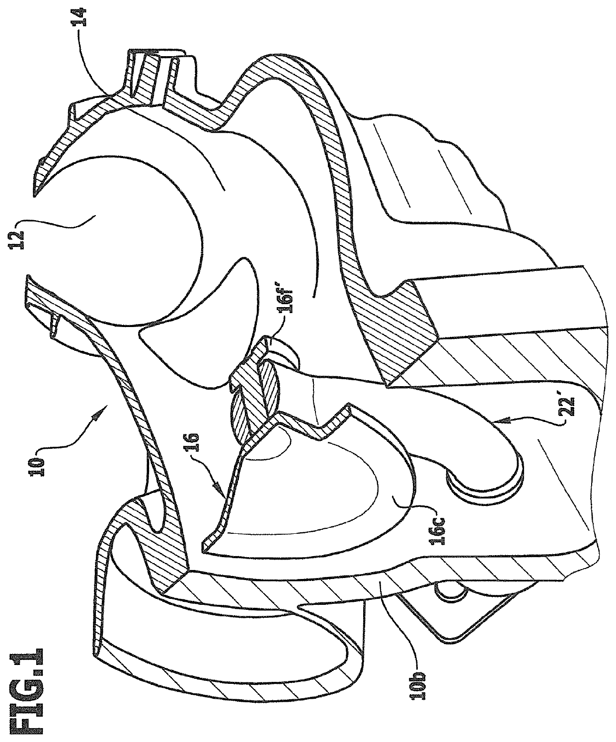
[0035]FIG. 1 shows a part of a turbine housing 10 into which the exhaust gas flow serving to drive an exhaust gas turbocharger turbine, not shown, enters through an exhaust gas inlet opening 12. Said exhaust gas inlet opening connects with an exhaust gas inflow path 14 formed in the turbine housing 10, which exhaust gas inflow path leads to the turbine, and a valve element 16, in this embodiment configured as a wastegate valve, is arranged in the exhaust gas inflow path. This valve element 16 of plate-like configuration, shown only partly in FIG. 1, can be moved in a manner described below in the exhaust gas inflow path 14 relative to the turbine housing 10, to enable...


PUM


Abstract

A valve device for an exhaust-gas bypass path of a turbocharger, including: a plate-like valve element, movable between a closed position and an open position and which has a shaft, which is connected to a valve element carrier for limited movement in the shaft direction; a rotatably held spindle, to which the valve element carrier is fixedly connected; a valve seat for the valve element, which valve seat surrounds an exhaust-gas through-opening; and an annular sheet-metal spring element, which has an opening through which the valve element shaft extends, an outer ring region, an inner ring region, which is axially offset relative to the outer ring region and adjoins the spring element opening, and an annular transition region therebetween; the width of the spring element transition region being variable around the spring element opening such that the valve element can be adapted to the valve seat as easily as possible.

Description

CROSS-REFERENCE TO RELATED APPLICATIONS[0001]This application is a continuation of International Patent Application No. PCT / EP2017 / 055612, filed Mar. 9, 2017, which claims priority to German Patent Application No. 10 2016 104 840.2, filed Mar. 16, 2016, which applications are hereby incorporated by reference in their entirety in this application.BACKGROUND OF THE INVENTION[0002]The invention relates to a valve device for an exhaust-gas bypass path of a turbocharger and has: a planar or plate-like valve element, which on one side thereof has a sealing surface and on the other side thereof has a shaft holding the valve element and is movable between a closed position and an open position; also a valve element carrier, to which the valve element is connected by means of its shaft, but nevertheless is movable to a limited extent relative to the valve element carrier in a direction perpendicular to the valve element sealing surface; furthermore a spindle, which is held (in particular in ...

Claims


Application Information

Patent Timeline
Patent Type & Authority Patents(United States)
IPC IPC(8): F02B37/18F02B37/12F16F1/32
CPCF02B37/186F02B37/12F02B37/18F02B37/183F05D2220/40F16F1/32Y02T10/12
Inventor HOFFMANN, MAXIMILIAN
Owner ELRINGKLINGER AG
Why Eureka
Try Eureka