Vertical axis wind turbine generator

a generator and vertical axis technology, applied in the direction of photovoltaic energy generation, motors, photovoltaic energy generation, etc., can solve the problems of delay in energy generation, prior art devices that do not protect blades and additional elements of the system, etc., and achieve the effect of protecting against high winds

Active Publication Date: 2021-07-13
ELEMENTAL ENG
View PDF14 Cites 0 Cited by
  • Summary
  • Abstract
  • Description
  • Claims
  • Application Information

AI Technical Summary

Benefits of technology

[0011]It is an objective of the present disclosure to provide an improved vertical axis turbine generator, in particular in terms of allowing a turbulence-free induced airflow when the turbine generator is in operation, which starts earlier to generate energy. In case the optimum position of the blades is not initially given, the device is self-sustaining by providing the necessary energy through the integrated solar panel which is not influenced by the function of the device. A battery is provided in the shaft of the device for storage of energy over night to be able to start and position the blades also in absence of natural light.
[0013]During turbine operation, the solar panel will preferably be positioned in a horizontal orientation. The solar panel can be mounted on the shaft to rotate with the shaft. In another embodiment, the solar panel is mounted on a non-rotating part of the shaft. The shaft then has a rotating part and a support stand extending part. The main central shaft is not necessarily a one piece element. One alternative uses a fixedly horizontally oriented solar panel which interferes the least with impending winds. It is also possible to use a switch reluctance mechanism to maintain the static orientation of the solar panel while the turbine system is in operation. Magnetic fields thus allow to maintain a stable platform and reduce frictional field and turbulence.
[0020]The vertical axis wind turbine generator can comprise only two blades. Then they will be mounted at an angular distance of 180° around the central shaft axis. For three blades, the angular distance between the three blades will be each time 120°. Of course it is also possible to provide 4, 5 or 6 blades with respective angular distances of 90°, 72° and 60°. Also, in the same way, higher numbers of blades are possible.
[0022]The blades are preferably attached at the connecting members at a fixed angle. Then, changing the effective radius of the blades when changing the state of deployment of the blades also alters the angle of attack of the vanes. This improves the overall solidity of the turbine system against different wind conditions, thereby altering the wind flow so as to be better harvestable, i.e. higher winds require less diameter than lower winds to generate the same torque required for the alternator of the system; thereby reducing overall demanded load on the gear arrangement.
[0024]The diameter of the solar panel is preferably predetermined such that the inner surfaces of the blades are near the outer circumference of the solar panel or—in a top view—are even under the solar panel, or are touching it at its outer circumference, when the blades are in their fully retracted state. When the inner surfaces of the blades are touching the outer circumference of the solar panel construction in a closed configuration, then the solar panel as well as the blades are better protected against high winds. The upper free ends of the blades are further preferably positioned—in a view from above—against the outer edge of the disc shaped solar panel, when the turbine is closed, especially under pre-load or pretension, when the curved connecting portions are retracted. Then the free ends of the blades are in maintained contact with the centrally mounted solar panel while the middle portion of the blades is in connection with the central shaft via the curved portions of the connecting members, so that no element of the device is prone to vibration.

Problems solved by technology

Another major difficulty of a vertical axis or Darrieus turbine is to make it self-starting.
Additionally, the blades are not always oriented in the optimum position, which may delay the energy generation.
Finally, some prior art devices do not protect blades and additional elements of the system, as e.g. a solar panel, from high winds.

Method used


Image

  • Vertical axis wind turbine generator
  • Vertical axis wind turbine generator
  • Vertical axis wind turbine generator

Examples


Embodiment Construction

[0040]The following describes in detail embodiments of the present disclosure. Examples of the embodiments are shown in the accompanying drawings, where reference signs that are the same or similar from beginning to end represent same or similar components or components that have same or similar functions.

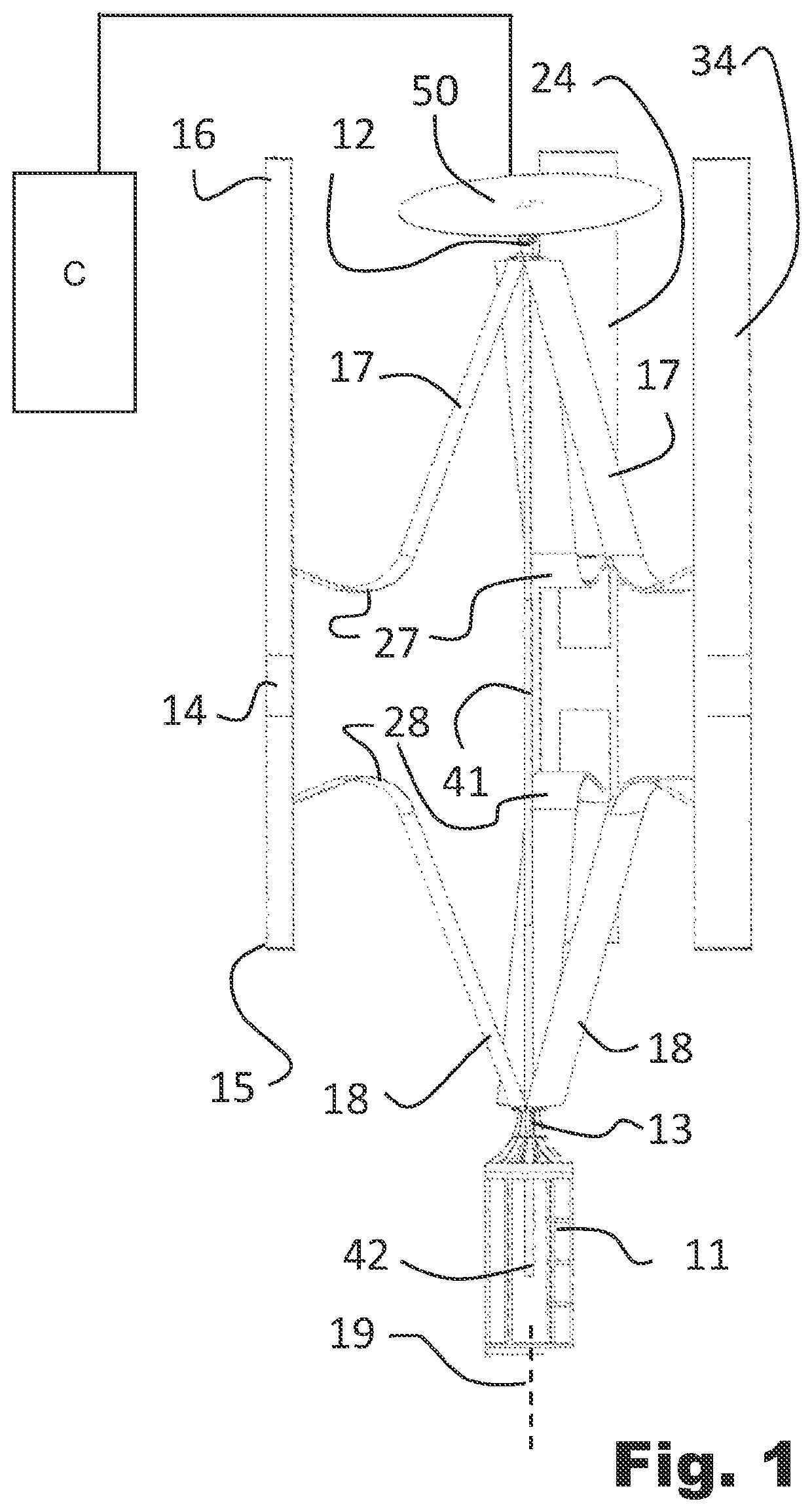
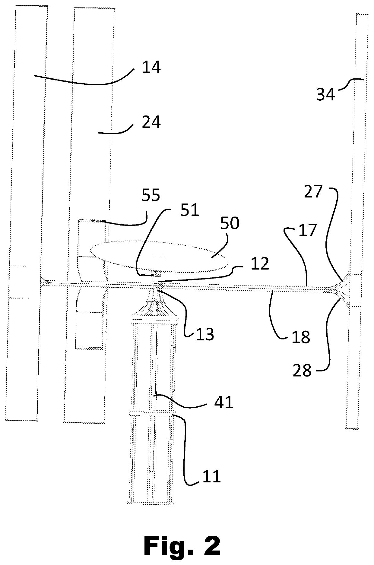
[0041]FIG. 1 shows a side view of a turbine according to an embodiment of the invention in a semi-closed configuration. FIG. 2 shows the same turbine in an open configuration. It is noted that the solar panel 50 is positioned horizontally (as better seen in FIGS. 5 and 8), the view of FIG. 2 is slightly from above to better distinguish the solar panel 50.

[0042]The vertical axis wind turbine generator comprises a support stand 11 positioned on a ground. It is essentially vertically oriented which is shown with longitudinal axis 19 of the generator. A telescopic shaft 41 (also denoted herein as center shaft) having a first end and a second end extends along said axis 19.

[0043]In one ...


PUM


Abstract

A vertical axis wind turbine generator having a support stand (11), a shaft (41) defining the longitudinal direction and axis (19) of the generator. Two rotating members (12, 13) are coupled to the support stand (11) and the upper end of the shaft (41), thus being enabled to rotate about the axis (19). Two or more blades (14, 24, 34) having two free ends (15, 16) are connected by connecting members (17 and 18) to the two rotating members (12, 13), wherein movement of the first and / or second rotating members (12, 13) towards or away from one another causes the blades (14, 24, 34) to move further from, or closer to, the shaft (41).

Description

CROSS REFERENCE TO RELATED APPLICATIONS[0001]This Application Is A National Stage Of International Application No. Pct / Ep2018 / 057842 Filed Mar. 27, 2018, Claiming Priority Based On European Patent Application No. 17163060.1 Filed Mar. 27, 2017.TECHNICAL FIELD[0002]The present invention relates to a vertical axis wind turbine generator comprising a support stand, a shaft having a first end, a second end and an axis extending in a longitudinal direction of the generator; a first rotating member coupled to a portion at the first end of the shaft, a second rotating member coupled to the support stand, wherein the first and second rotating members are able to rotate about said axis; two or more blades having two free ends, wherein a first blade portion related to the first free end is connected to the first rotating member by a first connecting member and a second blade portion related to the second free end is connected to the second rotating member by a second connecting member, enabli...

Claims


Application Information

Patent Timeline
Patent Type & Authority Patents(United States)
IPC IPC(8): F03D9/00F03D3/00F03D9/25H02S10/12
CPCF03D9/007F03D3/005F03D9/25H02S10/12F03D3/064F03D9/11Y02E10/50Y02E10/74Y02E70/30
Inventor SAEED, OSMAN
Owner ELEMENTAL ENG
Why Eureka
Try Eureka