Projection optical system and projector
a technology of projection optical system and projector, which is applied in the direction of projectors, mirrors, instruments, etc., can solve the problems of increasing the overall length of the optical system
- Summary
- Abstract
- Description
- Claims
- Application Information
AI Technical Summary
Benefits of technology
Problems solved by technology
Method used
Image
Examples
example 1
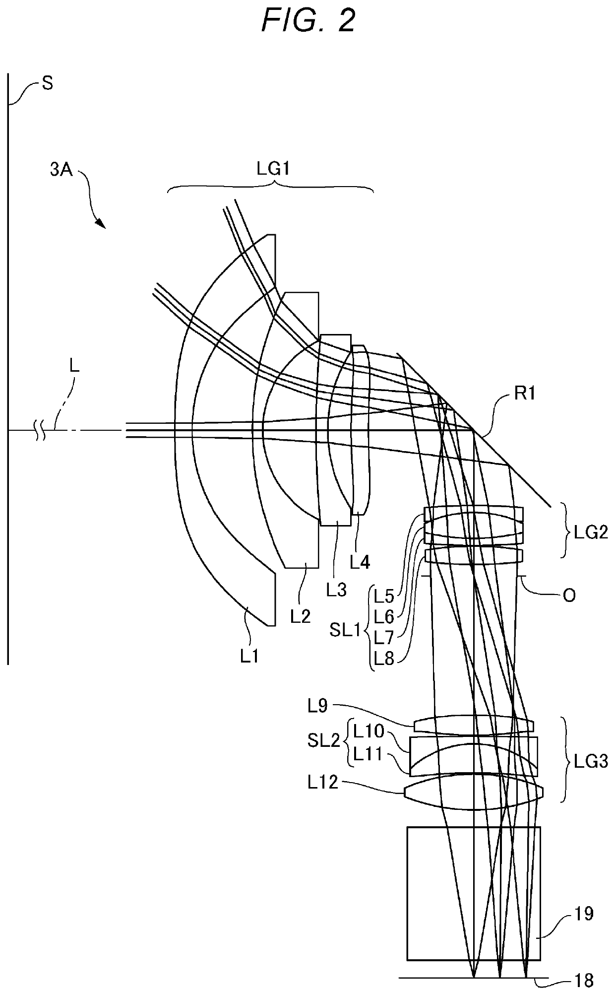
[0040]FIG. 2 is a light ray diagram of a projection optical system according to Example 1 including an optical path deflector. A projection optical system 3A according to the present example is formed of the following components sequentially arranged from the enlargement side: a first lens group LG1 having negative power; a second lens group LG2 having positive power; an aperture stop O; and a third lens group LG3 having positive power. The projection optical system 3A includes 11 lenses in total.
[0041]The projection optical system 3A includes an optical path deflector that is disposed between the first lens group LG1 and the second lens group LG2 and deflects the optical path, as shown in FIG. 2. In the present example, the optical path deflector is a mirror R1. In the projection optical system 3A, the mirror R1 bends an optical axis L by 90° in a position between the first lens group LG1 and the second lens group LG2. When the projection distance of the projection optical system 3...
example 2
[0081]FIG. 9 is a configuration diagram of the projection optical system according to Example 2. A projection optical system 3B according to the present example is formed of the following components sequentially arranged from the enlargement side: a first lens group LG1 having negative power; a second lens group LG2 having positive power; an aperture stop O; and a third lens group LG3 having positive power. The projection optical system 3B includes 9 lenses in total.
[0082]The projection optical system 3B includes an optical path deflector that is disposed between the first lens group LG1 and the second lens group LG2 and deflects the optical path, as shown in FIG. 9. The optical path deflector is a prism block P. The light modulator 18 is located in the reduction-side image plane of the projection optical system 3B. The screen S is located in the enlargement-side image plane of the projection optical system 3B. The projection optical system 3B includes the cross dichroic prism 19 be...
example 3
[0114]FIG. 16 is a light ray diagram of a projection optical system according to Example 3 including an optical path deflector. A projection optical system 3C according to the present example is formed of the following components sequentially arranged from the enlargement side: a first lens group LG1 having negative power; a second lens group LG2 having positive power; an aperture stop O; and a third lens group LG3 having positive power. The projection optical system 3C includes 9 lenses in total.
[0115]The projection optical system 3C includes an optical path deflector that is disposed between the first lens group LG1 and the second lens group LG2 and deflects the optical path, as shown in FIG. 16. In the present example, the optical path deflector is a mirror R1. In the projection optical system 3C, the mirror R1 bends an optical axis L by 90° in a position between the first lens group LG1 and the second lens group LG2.
[0116]The light modulator 18 is located in the reduction-side i...
PUM
 Abstract
Description
Claims
Application Information
 - R&D
- Intellectual Property
- Life Sciences
- Materials
- Tech Scout
- Unparalleled Data Quality
- Higher Quality Content
- 60% Fewer Hallucinations
Browse by: Latest US Patents, China's latest patents, Technical Efficacy Thesaurus, Application Domain, Technology Topic, Popular Technical Reports.
© 2025 PatSnap. All rights reserved.Legal|Privacy policy|Modern Slavery Act Transparency Statement|Sitemap|About US| Contact US: help@patsnap.com


