Asymmetrically-shaped isolator

a technology of isolators and asymmetrical shapes, which is applied in the field of isolation devices, can solve the problems of spacecraft components experiencing vibration and frequency, affecting instrumentation operation, performance, and/or output, and are subject to a wide range of potentially damaging environmental conditions

Active Publication Date: 2021-07-27
UNITED LAUNCH ALLIANCE
View PDF55 Cites 1 Cited by
  • Summary
  • Abstract
  • Description
  • Claims
  • Application Information

AI Technical Summary

Benefits of technology

[0008]Aspects of the present disclosure relate to a novel system, device, and methods for providing an isolator that limits a component's exposure to vibration, shock, and static or quasi-static loads, and also limits the component's exposure to thermal loads and electrical currents. The novel isolator described herein isolates the component from a range of vibration frequencies and distributes the effective modal mass across a range of frequencies while maintaining uniform or substantially uniform displacement under static and quasi-static loading. The novel isolator outperforms conventional vibration isolators in terms of cost, schedule (manufacturing time and lead time), heat dissipation, electrical isolation, and performance.

Problems solved by technology

Spacecraft are subjected to a broad range of potentially damaging environmental conditions during flight, including shock and vibration.
As a result, spacecraft components experience vibrations and frequencies that can affect the instrumentation's operation, performance, and / or output.

Method used


Image

  • Asymmetrically-shaped isolator
  • Asymmetrically-shaped isolator
  • Asymmetrically-shaped isolator

Examples


Embodiment Construction

[0102]Although the following text sets forth a detailed description of numerous different embodiments, it should be understood that the legal scope of the description is defined by the words of the claims set forth at the end of this disclosure. The detailed description is to be construed as exemplary only and does not describe every possible embodiment since describing every possible embodiment would be impractical, if not impossible. Numerous alternative embodiments could be implemented, using either current technology or technology developed after the filing date of this patent, which would still fall within the scope of the claims.

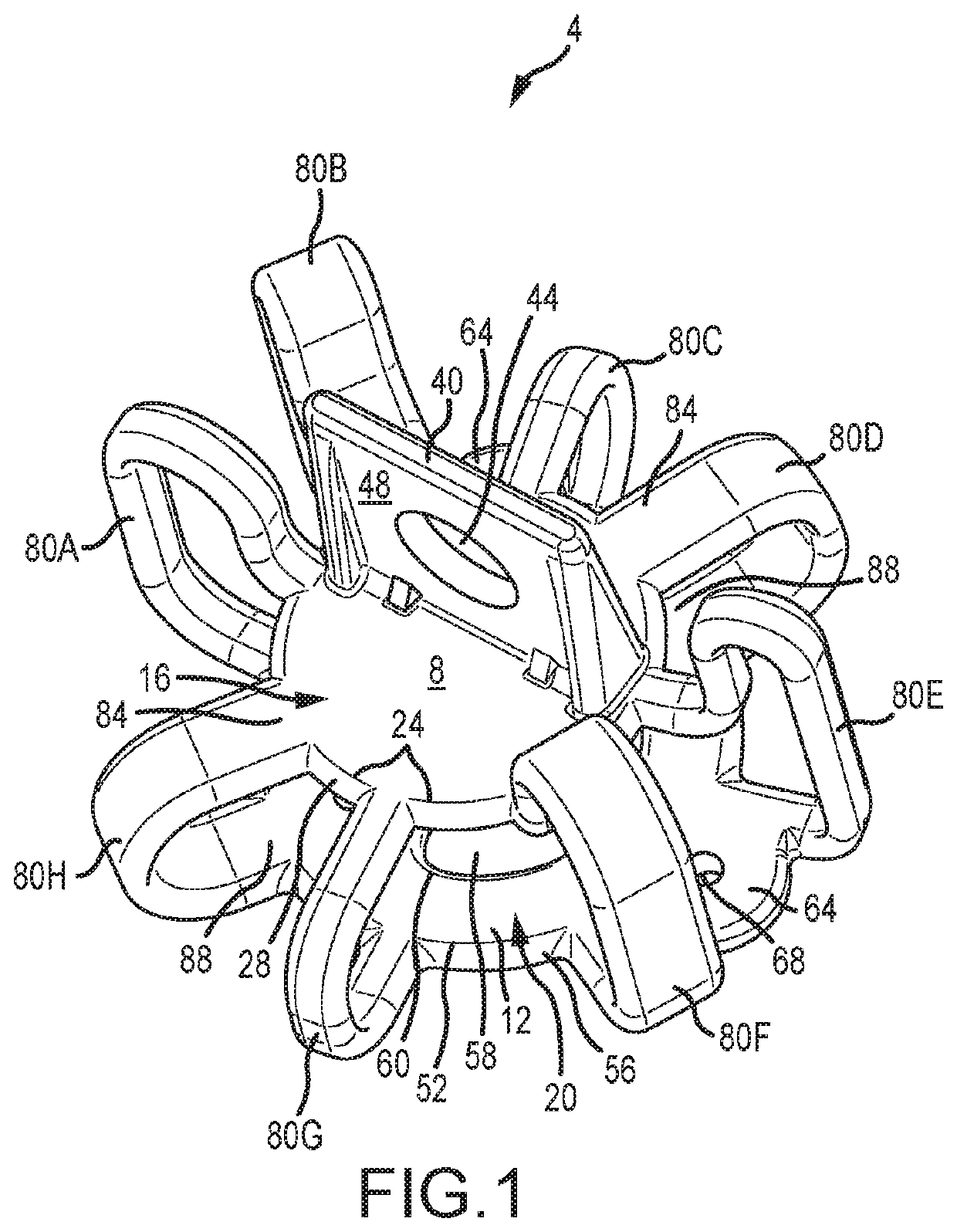
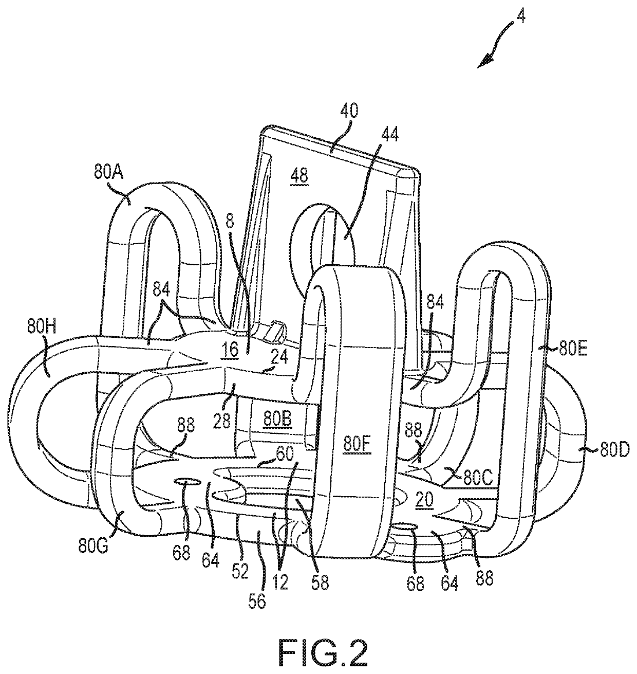
[0103]The orientation and directions as used herein are relative to the drawings as illustrated. Therefore, it should be appreciated that the terms “above,”“below,”“top,”“bottom,”“horizontal,” or “vertical,” are used to describe the relative location of different parts of the isolator (e.g., the lobes or platforms) and are intended to include not only ...


PUM

PropertyMeasurementUnit
frequencyaaaaaaaaaa
frequencyaaaaaaaaaa
frequencyaaaaaaaaaa

Abstract

Embodiments of the present invention generally relate to a novel system, device, and methods for providing an isolator for components and instrumentation to isolate vibrations, shock, static or quasi-static loads, thermal loads, and electrical currents. The novel isolator has an asymmetrical shape, experiences uniform motion under quasi-static loading, and reduces the effective modal mass across a range of frequencies. The novel isolator outperforms conventional vibration isolators in terms of cost, schedule (manufacturing time and lead time), heat dissipation, and performance.

Description

CROSS REFERENCE TO RELATED APPLICATION[0001]This application is a continuation application of and claims priority to U.S. patent application Ser. No. 15 / 636,139 filed Jun. 28, 2017, now U.S. Pat. No. 10,570,984, titled “ASYMMETRICALLY-SHAPED ISOLATOR”, which is incorporated by reference in its entirety herein.FIELD OF THE INVENTION[0002]Embodiments of the present invention generally relate to an isolator for components and instrumentation to isolate vibrations, shocks, static or quasi-static loads, thermal loads, and electrical currents, and more specifically to an asymmetrically-shaped isolation device that experiences uniform motion under quasi-static loading and that distributes the effective modal mass across a range of frequencies.BACKGROUND OF THE INVENTION[0003]Mission success of spacecraft, aircraft, and rockets is dependent upon components and instrumentation (collectively referred to as “components” herein) continuing to operate throughout an entire flight and beyond deplo...

Claims


Application Information

Patent Timeline
Patent Type & Authority Patents(United States)
IPC IPC(8): F16F15/08H01B17/56B64G1/22F16F1/36F16F1/373
CPCF16F15/08B64G1/22F16F1/36F16F1/373H01B17/56B64G2001/228F16F2222/02F16F2222/04F16F2226/04F16F2234/00B64G1/228
Inventor SHANNON, RYAN LEE
Owner UNITED LAUNCH ALLIANCE
Why Eureka
Try Eureka