Check patentability & draft patents in minutes with Patsnap Eureka AI!

Connector connection regenerating system and connector connection regenerating method

a technology of connector connection and regenerating system, which is applied in the direction of instruments, casings with connectors and pcbs, emergency protective circuit arrangements, etc., can solve the problems of poor connection, failure of a connector connection design, and undesirable countermeasures, so as to reduce costs

Active Publication Date: 2021-07-27
YAZAKI CORP
View PDF7 Cites 0 Cited by
  • Summary
  • Abstract
  • Description
  • Claims
  • Application Information

AI Technical Summary

Benefits of technology

Enables the cost-effective recovery of connector connections by removing foreign materials like oxide coatings, thereby reducing the need for complete system replacement and minimizing downtime.

Problems solved by technology

In addition to failures which occur at the side of a wire harness as described above, failures which occur at a design with a connector connection include poor connections which are caused by increase of a connection resistance between connector terminals unallowably e.g. due to a foreign material between the terminals, such as oxide coating.
Such a countermeasure is undesirable since the costs for failure tends to increase.
However, such a problem is not limited to a design using a connector connection e.g. for connecting a wire harness to an equipment, but can generally exist at any design with a connector connection.

Method used


Image

  • Connector connection regenerating system and connector connection regenerating method
  • Connector connection regenerating system and connector connection regenerating method
  • Connector connection regenerating system and connector connection regenerating method

Examples


first embodiment

[0017]Hereinafter, an embodiment of the present invention will be described. First, a first embodiment shall be explained.

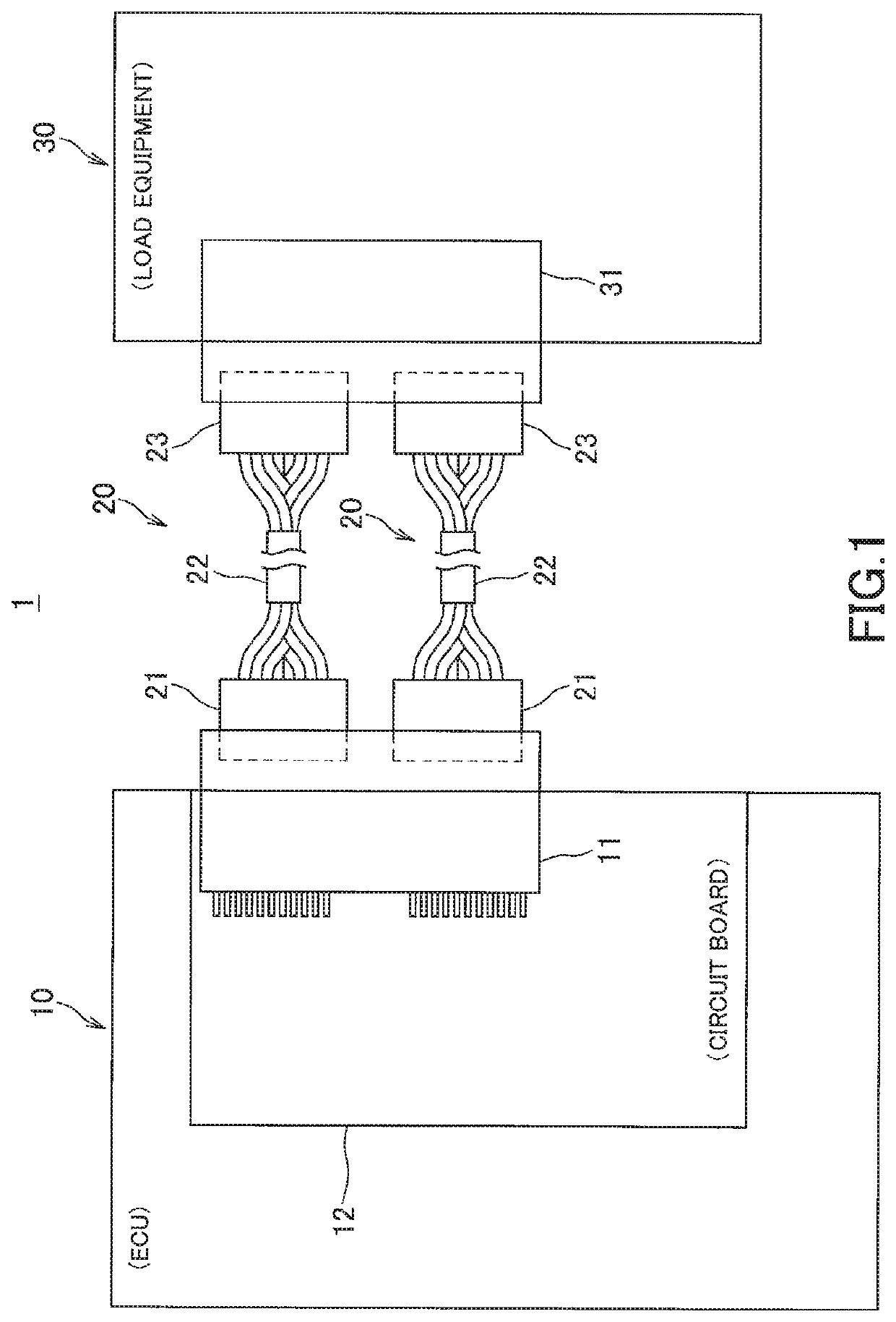
[0018]FIG. 1 is a schematic diagram illustrating an equipment connection structure to which a connector connection regenerating system according to the first embodiment of the present invention.

[0019]The equipment connection structure 1 according to the present embodiment is configured so that an ECU (Electronic Control Unit) 10 is connected to a predetermined load equipment 30 via two wire harnesses 20, wherein the ECU 10 is arranged in a vehicle and performs electric control processes for each of devices within the vehicle. The ECU 10 is equipped with an ECU connector 11 (first connector) as an equipment connector which forms an interface to an external system. The ECU connector 11 is a board connector which is mounted within the ECU 10 on a circuit board 12 undertaking various functions of the ECU 10. Each of the wire harnesses 20 includes a harness main body ...

second embodiment

[0066]FIG. 5 shows is a schematic diagram illustrating a harness connection structure for an ECU to which a connector connection regenerating system according to the present invention. It is to be noted that in FIG. 5, components similar to those shown in FIG. 1 are designated with the same reference signs as in FIG. 1, wherein explanation of these similar components shall not be repeated below.

[0067]A harness connection structure 5 according to the present embodiment is configured so that two wire harnesses 60 are connected to the ECU 50. The ECU 50 is equipped with a relay connector 51 as an equipment connector which forms an interface to an external system. An ECU connector 11 (first connector) is connected to the relay connector 51, the ECU connector 11 being mounted on a circuit board 12 within the ECU 50. Each of the wire harnesses 60 includes a harness main body 62 and an ECU-side harness connector 61 (second connector) which is provided at an end of the harness main body 62....


PUM


Abstract

The objective is to provide a connector connection regenerating system and a connector connection regenerating method which enable failures regarding connector connections to be solved with reduced costs when the failures have occurred. The objective is solved by a connector connection regenerating system comprising a regeneration circuit, a first connecting circuit connecting a first signal terminal (first terminal) switchably to a signal circuit and to the regeneration circuit, a ground circuit for conducting a regeneration current to a predetermined ground, a second connecting circuit connecting a second signal terminal (second terminal) switchably to a downstream circuit and to the ground circuit, and a controller configured to cause switching the first signal terminal (first terminal) to the regeneration circuit and switching the second signal terminal (second terminal) to the ground circuit.

Description

BACKGROUND OF THE INVENTIONTechnical Field[0001]The present invention relates to a connector connection regenerating system and connector connection regenerating method for recovering a connected status between a first terminal of a first connector and a second terminal of a second connector.Background Art[0002]Conventionally, a connector connection has been used e.g. for connecting a wire harness to an equipment etc. Here, the following method has been proposed as a countermeasure in case of some failure at the side of the wire harness. That is, it has been proposed for a type of wire harness which is mounted to an electronic device that the electronic device is attachable to and removable from a harness main body, wherein the electronic device is removed from the harness main body for exchange or repair when a failure has occurred at the electronic device (see e.g. Patent Document 1). With this method, it is not necessary to exchange the entire wire harness when a failure has occu...

Claims


Application Information

Patent Timeline
Patent Type & Authority Patents(United States)
IPC IPC(8): H02H7/00H01R43/00H02H7/20
CPCH01R43/00H02H7/20H01R43/26G06F1/189G06F1/266G01R31/69H05K5/0026
Inventor MATSUURA, SHINYA
Owner YAZAKI CORP
Features
  • R&D
  • Intellectual Property
  • Life Sciences
  • Materials
  • Tech Scout
  • Unparalleled Data Quality
  • Higher Quality Content
  • 60% Fewer Hallucinations
Learn More