Tackling machine

a tackling machine and tackling technology, applied in the field of tackling machines, can solve the problems of reducing the possibility of using the tackling machine at a new location, injuries to players, etc., and achieve the effect of maximizing its mobility

Active Publication Date: 2021-08-03
ANTONOV
View PDF6 Cites 0 Cited by
  • Summary
  • Abstract
  • Description
  • Claims
  • Application Information

AI Technical Summary

Benefits of technology

[0004]The aim of the invention is to provide a tackling machine, the movable element of which resembles the motion of a fast rolling rugby or American football player, and thus to improve the performance of competitors in the defense phase counteracting faster and more maneuverable strikers, whereby the tackling machine to allow easy relocation, if needed, due to damage of the playground grass or for other reasons and to allow installation on a scrum machine.
[0018]The advantages of the invention are that it provides training approach that is very close to the actual movement of the players on the sports field, including opportunities are insured for training of “persecution” of the opposing player and implementation of a complete blockage at place while the competitor is safe. The possibility for causing injuries is avoided through the use of a lightweight tackling dummy, while the workout site is free from any props that might lead to unwanted injuries. Moreover, the tackling machine can be mounted on the so called scrum machine, which on one hand will maximize its mobility, and will act as a natural weight on the scrum machine itself.

Problems solved by technology

The known tackling machine has drawbacks that create conditions for causing injuries to players because the training field is surrounded by columns and there is a possibility the athlete pursuing the tackling dummy to bump into any of them.
Moreover, the training field, fixed by the foundation columns, significantly reduces the possibility of using the tackling machine at a new location.

Method used


Image

  • Tackling machine
  • Tackling machine
  • Tackling machine

Examples


Embodiment Construction

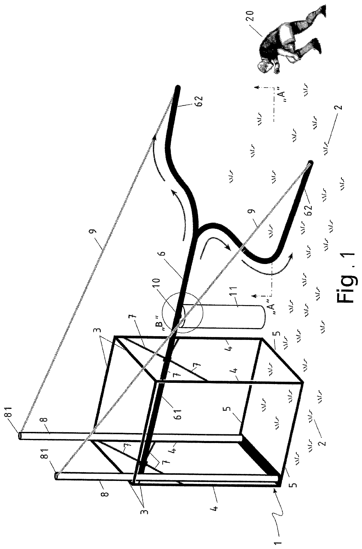
[0027]The tackling machine comprises a supporting frame structure 1, which may be constructed of metal such as steel, aluminum, titanium and / or suitable plastic materials. The supporting frame structure 1 is the heaviest part and is a basis for the entire tackling machine, and it is placed on the ground 2. It has the shape of a parallelepiped which includes all the elements forming the outline, namely upper girder elements 3, columns 4 and lower girder elements 5. For all the elements forming the supporting frame structure 1, a cross-section may be selected according to the particular design solution, including a circular cross-section tubular or solid. Installation of the bearing frame structure 1 is provided by either permanent connecting means such as welding, or, preferably, connecting means permitting assembly and disassembly, such as a bolt connections, which will allow easy transfer to another exercise area, where needed. The detachable connecting means are of known type. Whe...


PUM


Abstract

It is designed to train athletes in rugby and / or American football, providing movement very close to the actual one and gives possibility to be mounted on scrum machine. Tackling machine comprises supporting frame structure (1) with shape of a parallelepiped and detachable connecting devices interconnect its elements. It is placed on ground (2). The longitudinal guide (6) has forked end and is mounted to the structure (1) through the forward end (61). The forked end (62) of the longitudinal guide goes outside the structure (1). At least one metal rod (8) whose upper end (81) protrudes above the parallelepiped, and carry at least one tensioner (9), connected to the forked end (62). The drive unit (10) is mounted to the fork-shaped longitudinal guide and has a working area arranged outside the structure (1). The tackling dummy (11) is attached to the carrier (12) by a detachable connecting device (13).

Description

FIELD OF THE INVENTION[0001]The tackling machine is designed to train athletes practicing the sports rugby and / or American football.BACKGROUND OF THE INVENTION[0002]From US 2012 / 0309565 A1, a tackling machine is known comprising a supporting frame structure consisting of load-bearing upper girder elements with I-shaped cross-section, connected together in the shape of a rectangle. The upper girder elements are connected to the columns, founded into the ground. Lengthwise and centrally of the rectangle, a longitudinal guide is mounted, to which are connected the left and right guides disposed in the rectangular shape delineated by the upper girder elements. At the intersection of the three guides, a switching device is located. To the longitudinal guide, a drive unit is mounted constituting a bearing carriage, driven by a spring element. On the bearing carriage, a tackling dummy is suspended by a carrier. The drive unit has an operating area between the columns of the supporting fram...

Claims


Application Information

Patent Timeline
Patent Type & Authority Patents(United States)
IPC IPC(8): A63B69/34A63B21/00A63B21/005A63B21/008A63B71/02
CPCA63B69/345A63B21/0058A63B21/0085A63B21/4045A63B71/023A63B2071/025A63B2209/00A63B2210/50A63B71/0054A63B69/305A63B69/34
Inventor ANTONOV
Owner ANTONOV
Why Eureka
Try Eureka