
Piston internal combustion engine with generator

a technology of internal combustion engine and generator, which is applied in the direction of machine/engine, reciprocating combination engine, transportation and packaging, etc., can solve the problems of completely unbalanced reciprocating mass of crank mechanism, and achieve the effect of not increasing the installation height of the engine, no sensitive operation can be affected, and small in diameter

Active Publication Date: 2021-08-10
KNOB VACLAV
View PDF5 Cites 0 Cited by
  • Summary
  • Abstract
  • Description
  • Claims
  • Application Information

AI Technical Summary

Benefits of technology

The piston internal combustion engine with a generator meets the requirements of modern vehicles and airplanes for electrified power. It is a simple and inexpensive solution with only two cylinders that are balanced in terms of inertia forces and moments, resulting in no vibrations or force transmission to the engine mounts during operation. The engine can be easily installed, with a low profile and minimal load on the gearing. The use of identical generators and gears on both crankshafts further reduces the load on the gearing. The engine can be developed quickly and easily using components of contemporary single-cylinder engines.

Problems solved by technology

The reciprocating masses of the crank mechanisms remain completely unbalanced.

Method used


Image

  • Piston internal combustion engine with generator
  • Piston internal combustion engine with generator
  • Piston internal combustion engine with generator

Examples


Embodiment Construction

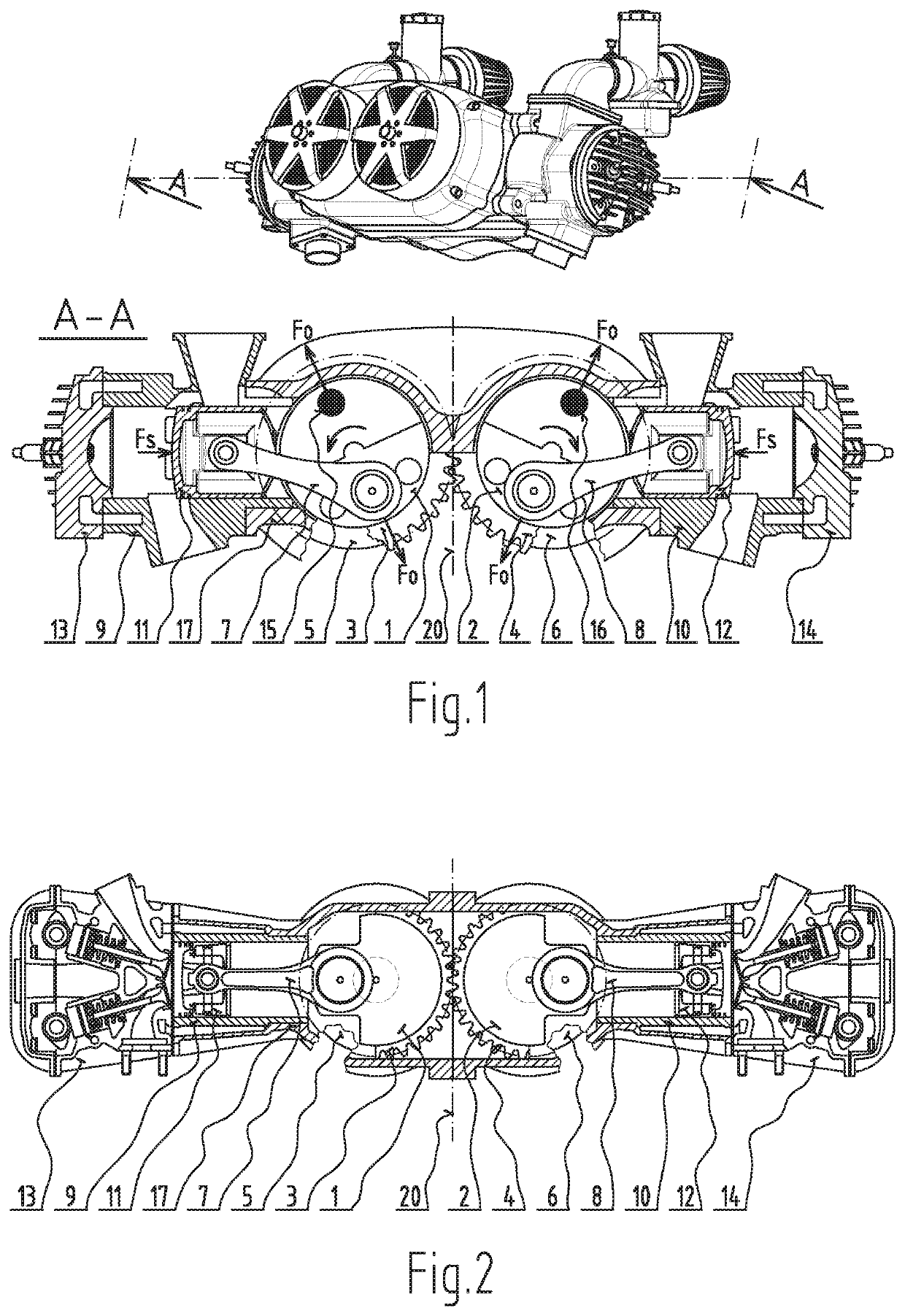
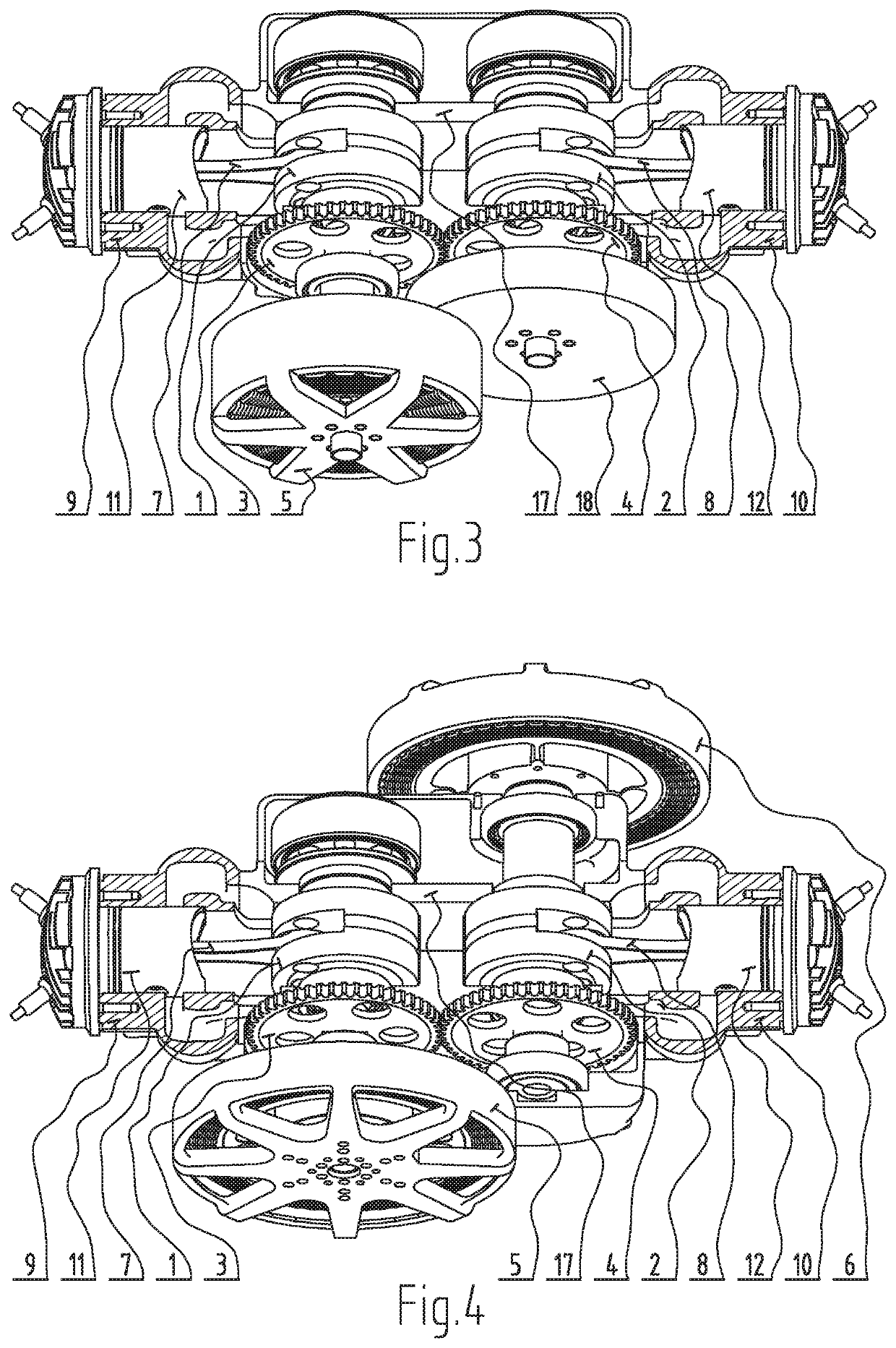
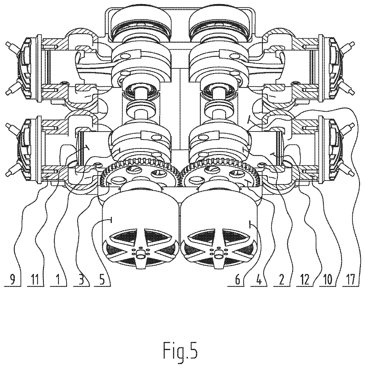
[0016]The model piston internal combustion engine of FIG. 1 consists of the two cylinders 9 and 10 with the cylinder heads 13 and 14 and the pistons 11 and 12 with the connecting rods 7 and 8 and two crankshafts 1 and 2, which are connected by the gears 3 and 4 with 1:−1 ratio, which means with the opposite direction of rotation. The first crankshaft 1 with the gear 3 is mounted parallel to the second crankshaft 2 with the second gear 4 in one engine case 17 such that the gears are engaged. The first crankshaft 1 is coupled to the first generator rotor 5 and the second crankshaft 2 is coupled to the second generator rotor 6. The moment of inertia of the first crankshaft assembly 1 with the first gear 3 and the first generator rotor 5 corresponds to the moment of inertia of the second crankshaft assembly 2 with the second gear 4 and the second generator rotor 6. The cylinders 9 and 10 with the pistons 11 and 12 are positioned perpendicular to the plane of symmetry 20 between the cran...


PUM


Abstract

A piston internal combustion engine with generator has two cylinders and cylinder heads and pistons with connecting rods and two crankshafts which are connected by gears with a ratio of 1:−1 (with opposite direction of rotation). The first crankshaft with the gear is mounted parallel to the second crankshaft with the second gear in one engine case such, that the gears engage. The first crankshaft is coupled to the first generator rotor and the second crankshaft is coupled to the second generator rotor or the flywheel. The moment of inertia of the first crankshaft assembly with the first gear and the first generator rotor is equal to the moment of inertia of the second crankshaft assembly with the second gear and the second generator rotor or flywheel. The cylinders with the pistons and are positioned perpendicularly to the plane of symmetry between the crankshafts, with the axes of the pair of cylinders lying in a plane with the both pistons being at the top dead center simultaneously.

Description

TECHNICAL FIELD[0001]The present invention relates to a piston internal combustion engine in coupling with a generator comprising a two-cylinder engine or engine with multiplication of two cylinders with two crankshafts for recharging accumulators in vehicles or airplanes with minimized vibration during operation, so-called range extender.BACKGROUND OF THE INVENTION[0002]Piston internal combustion engines of various types are used to drive a generator. Single and multi-cylinder units are used. Virtually every engine can be coupled to a generator, and so internal combustion engines based on engines for driving other devices are generally used. They usually have one crankshaft and drive one generator. These designs, although multi-cylinder and well balanced in terms of inertia forces, have torsional vibration, which is caused by individual firing events in the engine cylinders and the immediate reaction of the engine block. However, the requirements for modern generator drives in part...

Claims


Application Information

Patent Timeline
Patent Type & Authority Patents(United States)
IPC IPC(8): F02B75/06F16F15/26F01B1/10F02B75/22F02B75/32F02B75/02F02B75/18
CPCF02B75/065F16F15/265B60L2270/145F01B1/10F02B75/225F02B75/32F02B2075/027F02B2075/1808F02B63/042F02B75/24F01B21/02F16F15/26F16F15/24
Inventor KNOB, VACLAV
Owner KNOB VACLAV
Learn More