Efficient geothermal heat energy extraction system

a geothermal heat energy and extraction system technology, applied in the field of geothermal energy extraction, can solve the problems of increasing land subsidence, increasing geothermal pollution, and high inefficiency of active transportation of heating fluid through the pumping of heating fluid

Active Publication Date: 2021-08-10
SIDLABZ
View PDF7 Cites 0 Cited by
  • Summary
  • Abstract
  • Description
  • Claims
  • Application Information

AI Technical Summary

Benefits of technology

[0008]Providing the system with the features as disclosed above generates the advantage of having to implement the systems once, after which geothermal heat energy will be extracted passively thus efficiently, for example without having to use energy for example to transport the heat from the surrounding crust material to the well bottom part through natural heat conduction via at least one heat conductive path or for example to transport the heated heat medium by natural convection from the well bottom part to the well top part. More specifically, the passive, thus efficient, extracting of geothermal heat energy will be an efficient process for a longer time with respect to existing systems in the prior art as mentioned before, due to the enlarged area surrounding the geothermal well formed by the extending heat conductive paths, wherefrom heat will be extracted. The extraction of the geothermal heat energy from the surrounding crust material of the single geothermal well depends among other things on the contact surface area between the geothermal well and the surrounding crust material, for example largely determined by the surface area of the geothermal well wall, for example entirely determined by the geothermal well wall in the prior art single well geothermal heat extracting systems as mentioned earlier. The present invention solves the problem of efficiency present in the prior art systems by providing a heat conductive path in the crust material surrounding the geothermal well extending outwardly from the geothermal well into the crust material to conduct geothermal heat from the crust material surrounding the path towards the well bottom part, thereby increasing the contact surface area between the heat conductive materials such as the heat conductive path and the heat medium on the one hand, and the surrounding crust material on the other hand. Furthermore, as the heat conductive path extends away, i.e. outwardly from the geothermal well, the conductive path is reaching towards areas of crust material outside of the depletion zone, i.e. the zone of crust material in close vicinity from the single geothermal well more depleted from geothermal heat energy after a long term of heat harnessing than zones far away from the geothermal well, thus reaching zones less affected by the depletion and thus improving the long term efficiency i.e. longevity of the system.
[0085]The indirect use of the heated heat medium allows the user to be isolated from the heated heat medium which can for example be toxic or radioactive.

Problems solved by technology

Such approaches faced many different problems such as an increased geothermal pollution due to the creation of caustic water when traveling through the hot earth material from the injection well to the production well during which the water picks up minerals, salt and acidity; and such as an increased land subsidence due for example to the fracturing of earth material such as rock to create a passage from the injection well to the production well.
These looped single well geothermal energy extraction systems, relying on active transportation of the heating fluid through the pumping of the heating fluid are highly inefficient.
Although these passive single well geothermal heat extraction systems tend to have in certain situations an increased efficiency with respect to the looped single well geothermal heat extraction systems in terms of energy output with respect to energy input, these systems, much as other single well heat extraction systems and in contrast to for example EGS systems, are confronted with a lack of available heat in the earth material as the heat available in the relatively small area around the single well is being depleted rather quickly, thus limiting the efficiency for example on the long term of the geothermal heat extraction system.
Furthermore, as the efficiency of heat transfer depends on the contact area between the heat fluid and the heat source, for example the surrounding earth material, the efficiency of the single well applications is rather limited with respect to other systems such as EGS systems where the heat fluid is dispersed in the surrounding earth material travelling from the injection well to the production well.
The prior art however is only concerned with non-efficient closed loop single well geothermal heat energy extraction systems i.e. active heat energy extraction systems.

Method used


Image

  • Efficient geothermal heat energy extraction system

Examples


Embodiment Construction

[0086]Other details and advantages of the method of to the invention will become apparent from the enclosed figures and description of preferred embodiments of the invention.

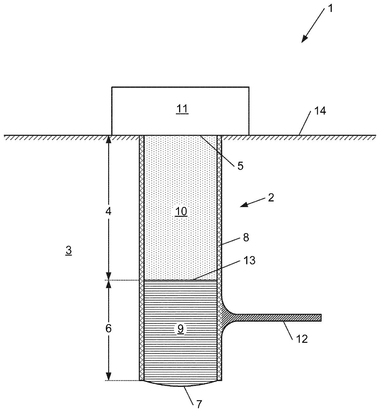
[0087]FIG. 1 shows a cross-section side view of the geothermal heat extraction system.

[0088]The FIG. 1 shows an embodiment of a geothermal heat extraction system 1 comprising an heat extractor 11 and a geothermal well 2, said geothermal well being provided within the crust material 3.

[0089]The crust material 3 is a part of the earth above the earth mantle and can consist of many different types of soils and rocks. The crust material extends in the direction opposed the gravitational acceleration vector up to a crust material surface 14 at which level the geothermal well 2 reaches a geothermal well top level 5 and at which level the heat extractor 11 is positioned. The geothermal well 2 extends in a first direction along the gravitational acceleration vector, from a well top part 4 starting at a well top level 5 ...


PUM


Abstract

A system for extracting geothermal heat energy: includes a geothermal well formed in surrounding crust material and extending from a well top part down to a depth where the surrounding crust material has elevated geothermal temperatures. The geothermal well includes a heat medium contained within geothermal well walls. The heat medium is heated at a well bottom part by heat extracted from the surrounding crust material, evaporating and rising to carry heat energy towards the well top part. A heat extractor, extracts heat energy from the heat medium at the well top part. At least one heat conductive path extends outwardly from the geothermal well into the crust material to conduct geothermal heat from the crust material surrounding the path towards the well bottom part.

Description

BACKGROUND OF THE INVENTION[0001]The present invention relates to the extraction of geothermal energy from earth material such as earth crust material, more particularly to the efficient recovery of geothermal energy from earth material.[0002]The rapidly diminishing sources of fossil fuels, combined with the polluting effects of the energy source as well as of alternatives such as nuclear energy sources, has resulted in a number of prior art attempts to convert the heat available in the earth material to alternative energy such as electrical energy. Some prior art approaches require multiple wells to be drilled in the earth material for example enhanced geothermal systems (EGS) where an injection well is provided, configured to pump a fluid such as water into the earth material where it heats up and wherefrom it is subsequently retrieved through a production well provided at some distance from the injection well. Such approaches faced many different problems such as an increased geo...

Claims


Application Information

Patent Timeline
Patent Type & Authority Patents(United States)
IPC IPC(8): F24T10/30F24T10/40F24T10/13F28D15/02F24T10/00
CPCF24T10/30F24T10/13F24T10/40F28D15/02F24T2010/50Y02E10/10F28F1/124F28F1/24
Inventor GHEYSENS, SIMON MAURICE
Owner SIDLABZ
Why Eureka
Try Eureka