Diffractive grating with variable diffraction efficiency and method for displaying an image

a technology of diffractive gratings and diffraction efficiency, which is applied in the field of diffractive gratings, can solve the problems of low yield of this process, high optimization and complex processing of materials, and difficult fabrication of micro- and nanostructures with varying heights on the same substrate, and achieve the effect of optimizing the optical performance of optical systems and modulating the diffraction efficiency of gratings

Active Publication Date: 2021-08-10
DISPELIX OY
View PDF12 Cites 1 Cited by
  • Summary
  • Abstract
  • Description
  • Claims
  • Application Information

AI Technical Summary

Benefits of technology

[0009]According to one aspect, the invention is based on providing in a diffractive grating a two-dimensional grating period, where one of the two perpendicular grating periods is large enough to generate diffraction while the other grating period is sub-wavelength, and can be applied for efficiency modulation. In particular, the spacing between adjacent structures, i.e. fill factor modulation, in this direction can be used to modulate the diffraction efficiency.
[0012]The present diffractive display device comprises an image source capable of presenting an image and a diffractive waveguide comprising an in-coupling grating, an out-coupling grating, and / or an exit pupil expander grating of the kind described above configured to reproduce the image presented by the image source. In particular, the image source has an output wavelength or wavelength range and the second period of the grating is in the sub-wavelength region of the image source for preventing diffraction in the second direction.
[0016]The invention offers significant benefits. First, the invention allows for a large modulation capability of diffraction efficiency without the need of height modulation of the structures that is generally regarded very challenging. In particular the invention allows, even without height modulation, for achieving diffraction efficiency adjustment range, which is similar to that previously achieved using simultaneous fill factor and height modulation in the primary diffraction direction. Thus, the invention can be used to remove the tedious need of grating height adjustment and replaces it by a sub-wavelength modulation in a fill factor for example in the perpendicular direction of the primary grating direction grating.
[0017]By providing a completely new design option having an effect on the diffraction efficiency, the invention addresses the need for design parameters for diffractive gratings in which the diffraction efficiency can be freely adjusted. The new design parameter, sub-wavelength modulation, assists in adjusting the diffraction efficiency locally in particular in display applications. Applied e.g. in an in-coupling grating, exit pupil expander and / or out-coupling grating of a diffractive NED or HUD, the color balance, image uniformity and / or efficiency (brightness) of the resulting image can be optimized.
[0021]In some embodiments, the first zone and the second zone have different fill factor modulation characteristics in said second direction. In some embodiments, this is the only modulation method used in the second direction, which makes the manufacturing process simpler, because no local modification of height is needed. However, it is not excluded that the first zone and the second zone have, in addition to or instead of fill factor modulation, different height modulation characteristics in the second direction.
[0023]In some embodiments, the grating structures are at least partly made of material having an index of refraction higher than 1.7, such as higher than 2.0, the material preferably being an oxide material, such as a metal oxide or nitride, for example TiO2, SiO2, Si3N4 or HfO2. These materials allow for producing high quality gratings on high refractive index substrates.

Problems solved by technology

In particular, fabrication of micro- and nanostructures with varying heights on a same substrate is difficult especially in the case of inorganic materials that are difficult to process.
This also requires highly optimized and often complicated processing of the material.
Because of the complexity of the method, the yield of this process is low.
Moreover, overlay exposure requires lateral placement accuracy in nanometer level, and any deviations from optimal causes losses in optical performance.
Typically overlay exposure has an accuracy of ˜10 nm, which causes significant deviations to optimal optical performance.
Accurate height modulation is by itself challenging and particular challenges are faced when both height modulation and fill factor modulation are desired in order to achieve maximum efficiency adjustment range.
The need of height modulation, however, increases the fabrication complexity especially in the case of high refractive index materials, such as oxides.
There are few methods available that suit for mass production.

Method used


Image

  • Diffractive grating with variable diffraction efficiency and method for displaying an image
  • Diffractive grating with variable diffraction efficiency and method for displaying an image
  • Diffractive grating with variable diffraction efficiency and method for displaying an image

Examples


Embodiment Construction

Definitions

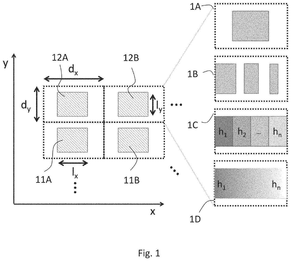
[0036]“First direction” and “primary direction” refer to the direction of the grating in which the actual diffraction takes place in the particular zone concerned, i.e. the direction in which the grating pattern periodicity is in the optical diffractive range.

[0037]“Second direction” and “secondary direction” refer to the sub-wavelength periodicity direction of the grating pattern used for diffraction efficiency modulation.

[0038]“Lateral” and “in-plane” refer to the plane defined by the first direction and the second direction. Typically, this corresponds to the plane of a planar substrate the grating is manufactured on. “Normal” direction refers to the direction perpendicular to the lateral plane.

[0039]The term “zone” (like in “first zone” and “second zone”) refers to a region of the grating in the lateral plane, the region having the characteristics, in particular sub-wavelength modulation characteristics, referred to in each case. Typically, the zones are discrete, whe...


PUM

PropertyMeasurementUnit
areaaaaaaaaaaa
areaaaaaaaaaaa
transmittanceaaaaaaaaaa

Abstract

The invention relates to a diffractive optical grating and applications thereof. The grating comprises a first zone and a second zone each having a two-dimensionally periodic grating structure having a first period (dx) in a first direction, the first period being chosen to allow for diffraction of selected wavelengths of visible light along the first direction, and a second period (dy) in a second direction different from the first direction, the second period (dy) being short enough to prevent diffraction of said selected wavelengths along the second direction. According to the invention, the grating structures in the first zone and in the second zone have different modulation characteristics in said second direction for producing different diffraction efficiencies for the first and second zones. The invention provides a new design parameter, sub-wavelength modulation, for assisting in local adjustment of diffraction efficiency of gratings in particular in display applications.

Description

FIELD OF THE INVENTION[0001]The invention relates to diffractive gratings, and in particular their use in display technology. Specifically, the invention relates to a diffraction efficiency-modulated grating, optical devices utilizing such grating and a method for displaying an image on a diffractive display, and a novel use.BACKGROUND OF THE INVENTION[0002]Near-to-eye displays (NEDs) and head-up displays (HUDs) typically involve diffractive gratings to produce a viewable image. Gratings are needed as in-coupling gratings, which couple an image from an image source to a wave guide, as out-coupling gratings, which produce the final viewable image for the user, and as exit pupil expanders (EPEs), which increase the size of the displays exit pupil.[0003]The quality and characteristics of the gratings determine the quality of resulting image. In addition to having distinct and consistent grating lines, in advanced applications it is desirable to be able to control the diffraction effici...

Claims


Application Information

Patent Timeline
Patent Type & Authority Patents(United States)
IPC IPC(8): F21V8/00
CPCG02B6/0038G02B6/0016G02B5/1828G02B5/1842G02B5/188G02B2027/0125G02B27/0172G02B27/4272G02B27/0081G02B6/34G02B5/1809G02B5/1819
Inventor VARTIAINEN, ISMOOLKKONEN, JUUSORAHOMÄKI, JUSSI
Owner DISPELIX OY
Why Eureka
Try Eureka