
Side supporting type vehicle roof tent

a technology of supporting type and roof tent, which is applied in the field of tents, can solve the problems of high cost, high market price, and relatively complicated support structure of the entire tent, and achieve the effects of low cost, easy folding or unfolding, and simple structur

Active Publication Date: 2021-09-07
Q YIELD OUTDOOR GEAR
View PDF40 Cites 0 Cited by
  • Summary
  • Abstract
  • Description
  • Claims
  • Application Information

AI Technical Summary

Benefits of technology

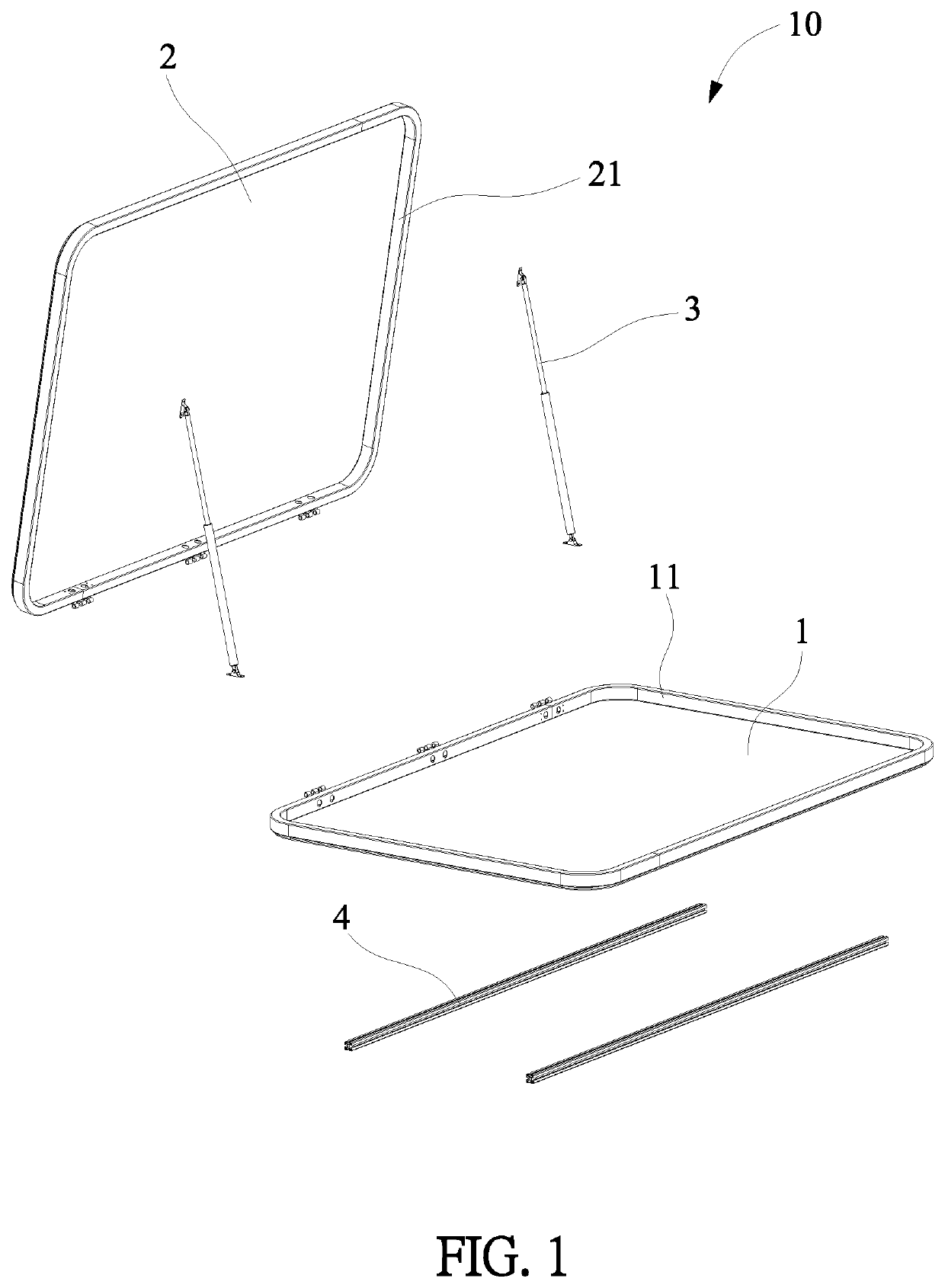
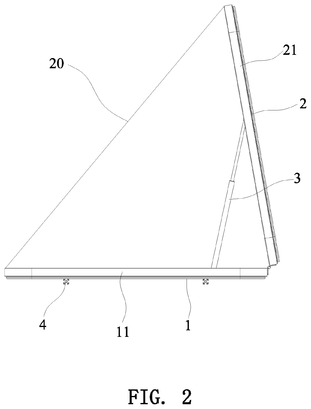
The present invention provides a side supporting type vehicle roof tent that is simple, easy to unfold or fold, and low in costs. The tent is designed with a rear end pivotally connected to the base and a support connecting rod between the base and the top cover, allowing for easy unfolding and folding of the tent. The front end of the top cover only needs to be controlled to be unfolded or folded with respect to the front end of the base, and the tent cloth unfolds or folds with the tent rack in a linkage manner. This tent has a simple structure, is easy to use, and is cost-effective, making it a competitive option in the market.

Problems solved by technology

However, the support structure of the entire tent is relatively complicated and the cost is high, which causes the market price to remain high.

Method used


Image

  • Side supporting type vehicle roof tent
  • Side supporting type vehicle roof tent
  • Side supporting type vehicle roof tent

Examples


first embodiment

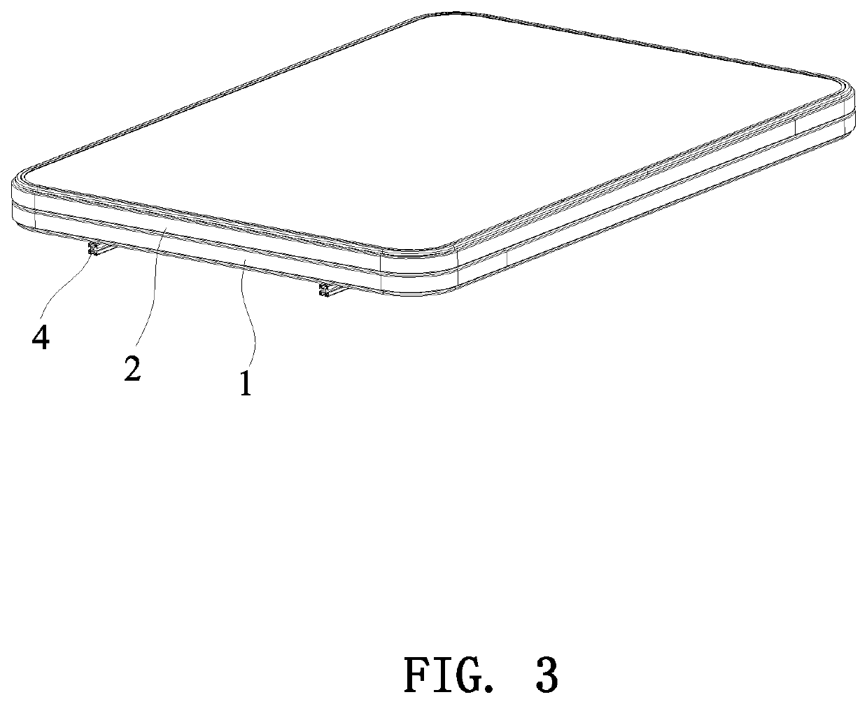
[0031]FIGS. 1 to 3 illustrate the present invention. Wherein, a mounting rail 4 may be installed to the bottom of the base 1. Through the mounting rail 4, the present invention can be installed and fixed to a luggage rack on the top of a vehicle. The top cover 2 may be a frame structure or a cover structure. There are different means for pivoting the base 1 and the top cover 2. In this embodiment, the base 1 and the top cover 2 are pivotally connected together by three hinges arranged at intervals, so that the front end of the top cover 2 can be unfolded or folded relative to the base 1.

[0032]A retaining wall 21 is provided on the outer periphery of the top cover 2 facing the base 1. A raised wall 11 is provided on the outer periphery of the top of the base 1. The retaining wall 21 corresponds to the raised wall 11. The tent cloth 20 is disposed between the retaining wall 21 and the raised wall 11.

[0033]The support connecting rod 3 may be one or more than one in number. When one sup...

second embodiment

[0037]FIGS. 4 to 6 illustrate the present invention. The second embodiment is substantially similar to the first embodiment with the exceptions described hereinafter. The tent rack 10 further includes a front support rod 5. The front support rod 5 is a U-shaped rod having two vertical rods 51, a transverse rod 52, and a U-shaped opening 53 facing downward. The two vertical rods 51 of the front support rod 5 are pivotally connected to the front end of the base 1. The tent cloth 20 is fitted on the transverse rod 52 of the front support rod 5. The opening of the tent cloth 20 is disposed in the U-shaped opening 53 of the front support rod 5. Compared with the first embodiment, the second embodiment is provided with the front support rod 5 to greatly increase the space of the tent. When the tent is unfolded or folded, the front support rod 5 will be unfolded or folded along with the tent cloth 20. For the front support rod 5 to be smoothly retracted within the base 1 and the top cover ...


PUM


Abstract

A side supporting type vehicle roof tent comprises a tent rack and a tent cloth fitted inside the tent rack. The tent rack comprises a base, a top cover, and at least one support connecting rod; the rear end of the top cover is pivotally connected to the rear end of the base; the support connecting rod is provided between the base and the top cover; one end of the support connecting rod is connected to the top cover, and the other end is connected to the base; the tent cloth is provided between the top cover and the base in a matching manner; the tent cloth between the front end of the top cover and the front end of the base is provided with an opening. The tent is simple in structure and easy to unfold or fold.

Description

BACKGROUND OF THE INVENTION1. Field of the Invention[0001]The present invention relates to a tent, and more particularly, to a side supporting type vehicle roof tent.2. Description of the Prior Art[0002]The continuous increase of privately owned cars allows travels by self-driving a new way of enjoying trips. To suit the need of people for driving to travel by themselves, products attachable to cars to help people to make the self-driving trips and tents for cars have been developed for such a need.[0003]A tent for cars may be structured for installation on the roof of a car. This makes the tent different from the regular camp tents by being set distant from the ground when it is set up so as to help prevent the invasion of moisture and cold air from the ground, making it more comfortable in use. Car roof tents are known, such as Chinese Patent CN201531147U, issued on Jul. 21, 2010; CN202187605U, issued on Apr. 11, 2012; and CN203213695U, issued Sep. 25, 2013.[0004]The conventional ...

Claims


Application Information

Patent Timeline
Patent Type & Authority Patents(United States)
IPC IPC(8): E04H15/06E04H15/48B60P3/38
CPCE04H15/06B60P3/38E04H15/48B60P3/343E04H15/34B60P3/34
Inventor JIN, QIUZHOU, NANQINGMAO, MUHUACHEN, MING
Owner Q YIELD OUTDOOR GEAR
Learn More