EGR system of engine

Active Publication Date: 2021-09-07
MAZDA MOTOR CORP
View PDF5 Cites 0 Cited by
  • Summary
  • Abstract
  • Description
  • Claims
  • Application Information

AI Technical Summary

Benefits of technology

The present invention provides an exhaust gas recirculation system for an engine that improves the drainage of the system without compromising its cooling performance and reduces the overall height of the system.

Problems solved by technology

However, the engine is installed in a limited space of an engine bay.
In this case, it becomes difficult to secure the at least given size of gap.
For this reason, it is not easy to improve a drainage property of condensed water by simply tilting the EGR cooler.

Method used


Image

  • EGR system of engine
  • EGR system of engine
  • EGR system of engine

Examples


Embodiment Construction

[0045]Hereinafter, one embodiment of a present disclosure is described. Note that the following description is merely an example and is not to limit the present invention, its application, or its use.

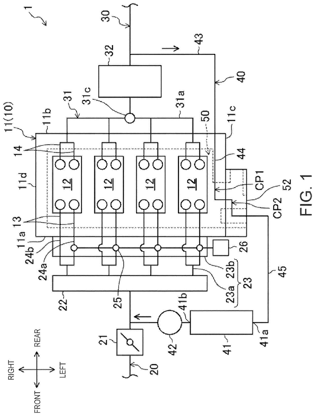
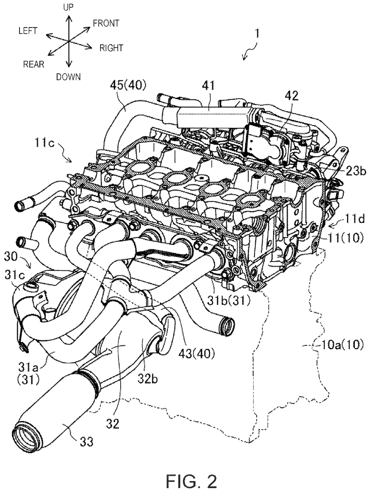
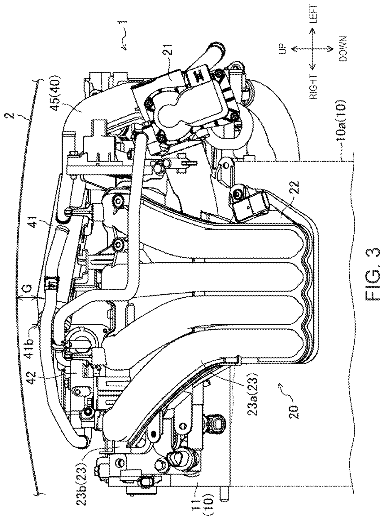
[0046]FIG. 1 is a diagram illustrating main devices of an exhaust gas recirculation (EGR) system integrally configured with an engine (hereinafter, collectively referred to simply as the “engine 1”). FIG. 2 is a schematic perspective view specifically illustrating an overall structure of the engine 1. FIG. 3 is a schematic front view of an upper part of the engine 1. FIG. 4 is a schematic view of the upper part of the engine 1, seen from a side of a first end surface 11c of a cylinder head 11. FIG. 5 is a schematic perspective view of the upper part of the engine 1, seen from an obliquely upper side thereof. FIG. 6 is a schematic perspective view illustrating a part of the engine 1 in an enlarged manner.

[0047]Arrows illustrated in the drawings indicate directions of “front and rear,”“le...


PUM


Abstract

An engine EGR system is provided. An EGR passage includes an EGR cooler, an EGR internal passage passing through a cylinder head on an upstream side of the EGR cooler, and a relay passage extending outside the cylinder head and connecting the EGR internal passage to the EGR cooler. The EGR cooler formed in a columnar shape is arranged above an intake manifold so as to locate a gas inflow port on a first end surface side and a gas outflow port on a second end surface side, and the relay passage communicates with the EGR internal passage on an external side of the engine compared to a head EGR gas exit. The EGR cooler inclines downward from the gas outflow port toward the gas inflow port, and the relay passage is connected to the gas inflow port while being bent downward toward the upstream side.

Description

TECHNICAL FIELD[0001]The present disclosure relates to an exhaust gas recirculation (EGR) system of an engine.BACKGROUND OF THE DISCLOSURE[0002]There is known a technology for engines for driving a vehicle, etc., that brings a portion of exhaust gas (also referred to as EGR gas) back into intake gas, so-called EGR (Exhaust Gas Recirculation). A majority of EGR systems that perform EGR are usually installed with an EGR cooler to cool high-temperature EGR gas.[0003]Regarding the disclosed technology, JP2016-102429A discloses an engine in which an EGR cooler is disposed on an upper part of an intake manifold.[0004]Condensed water containing oxidizing substances is generated inside the EGR cooler. Therefore, when the EGR cooler is placed transversely as in the engine of JP2016-102429A, it is preferred to avoid the condensed water from accumulating in the EGR cooler. For this, a considerable general method is to tilt the EGR cooler and flow the condensed water down.[0005]However, the eng...

Claims


Application Information

Patent Timeline
IPC IPC(8): F02M26/23F02M26/21F02D41/14F02D41/00F02M26/41
CPCF02M26/23F02D41/0052F02D41/0077F02D41/1454F02M26/21F02M26/41F02M26/13F02M26/28F02M26/29F02M26/30F02F1/24F02F1/42F02M26/12F02M26/24F02M26/32F02M26/35
Inventor FUJIHIRA, SHINJIKINOSHITA, HIROSHIKARIYA, TAKASHITOMINAGA, TAKAYUKIYOSHIDA, KEN
Owner MAZDA MOTOR CORP
Why Eureka
Try Eureka