Power converter

a power converter and converter technology, applied in the field of power converters, can solve the problems of difficult accurate use, low resolution of current detectors with large magnitude, and low resolution of current detectors, so as to facilitate the change of the amount of current, the effect of detecting the current flow and reducing the difficulty of accuracy

Active Publication Date: 2021-09-07
FUJI ELECTRIC CO LTD
View PDF3 Cites 2 Cited by
  • Summary
  • Abstract
  • Description
  • Claims
  • Application Information

AI Technical Summary

Benefits of technology

[0006]The present invention was made to solve the abovementioned problems, and one object of the present invention is to provide a power converter which makes it possible to improve charge current control accuracy.
[0016]As described above, the present invention makes it possible to improve charge current control accuracy.

Problems solved by technology

Moreover, current detectors that are capable of detecting currents of large magnitude typically have relatively low resolution.
In this case, using such a current detector that has relatively low resolution is disadvantageous because it becomes difficult to accurately detect the charge current (which has relatively small magnitude).
Therefore, due to the low charge current control accuracy, battery overcharging or the like can occur and cause problematic degradation of the battery.

Method used


Image

  • Power converter
  • Power converter
  • Power converter

Examples


embodiment 1

Effects of Embodiment 1

[0051]Embodiment 1 makes it possible to achieve the following advantageous effects.

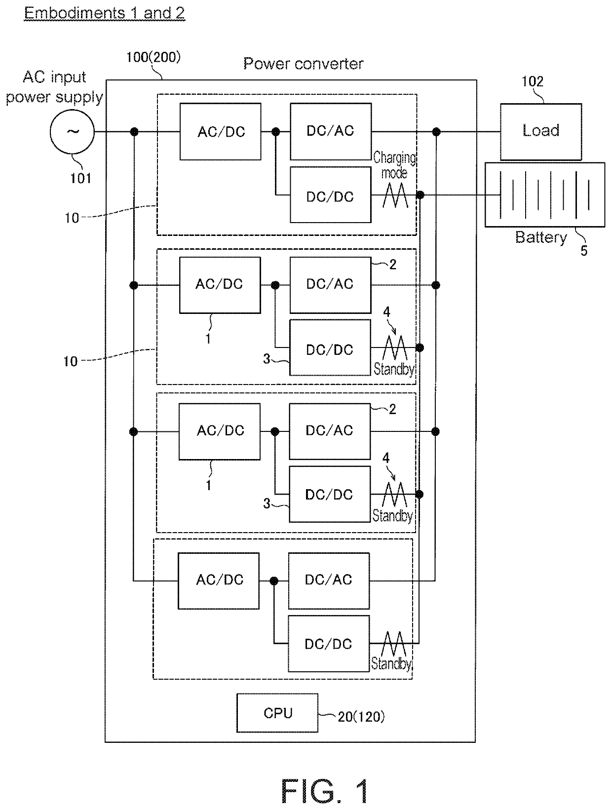
[0052]As described above, in Embodiment 1 the power converter 100 is configured to include the battery 5 that is charged by a subset of DC / DC converters 3 among the DC / DC converters 3 of the plurality of power conversion units 10, as well as the CPU 20 that controls the DC / DC converters 3 of the plurality of power conversion units 10. Here, the charge current that flows to a single current detector 4 takes a value equal to the charge current that flows to the battery 5 divided by the number of power conversion units 10 (DC / DC converters 3) being used for charging. Thus, charging the battery 5 using a subset of DC / DC converters 3 among the DC / DC converters 3 of the plurality of power conversion units 10 makes it possible to increase the charge current that flows to a single current detector 4 in comparison to if all of the DC / DC converters 3 were used for charging. As a result, e...

embodiment 2

Effects of Embodiment 2

[0062]Embodiment 2 makes it possible to achieve the following advantageous effects.

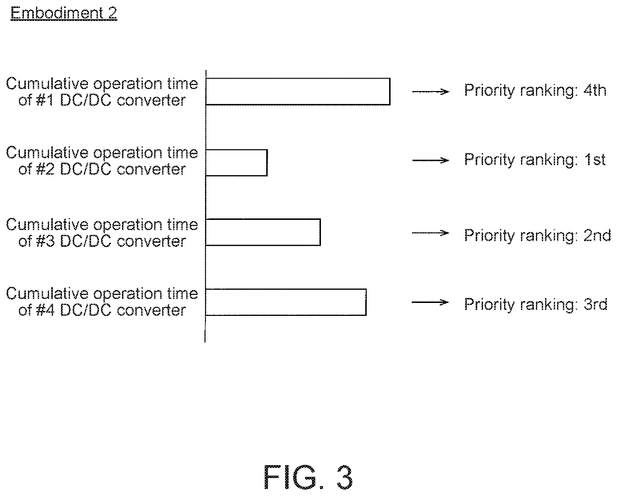
[0063]As described above, in Embodiment 2 the power converter 200 is configured such that the CPU 120 selects the DC / DC converters 3 in the subset that charges the battery 5 in order starting from the DC / DC converter 3 with the highest priority ranking, as determined on the basis of the cumulative operation times of the DC / DC converters 3, among the DC / DC converters 3 of the plurality of power conversion units 10. This makes it possible to prevent DC / DC converters 3 with longer cumulative operation times and a greater degree of degradation from being used to charge the battery 5. This, in turn, makes it possible to inhibit degradation of (damage to) the DC / DC converters 3.

[0064]The rest of the effects of Embodiment 2 are the same as in Embodiment 1.

modification examples

[0065]It should be noted that in all respects, the embodiments described above are only examples and do not limit the present invention in any way. The scope of the present invention is defined by the claims, not by the descriptions of the embodiments above. Furthermore, the scope of the present invention also includes all changes (modification examples) made within the scope of the claims and their equivalents.

[0066]For example, although in Embodiments 1 and 2 above the number of active DC / DC converters 3 (DC power converters) in the subset was described as being changed on the basis of the detected values from the current detectors 4 as an example, the present invention is not limited to this example. For example, the number of active DC / DC converters 3 (DC power converters) in the subset may be changed on the basis of the current flowing to the load 102 from the DC / AC converters 2 (AC power converters).

[0067]More specifically, as illustrated in FIG. 4, a power converter 300 inclu...


PUM


Abstract

A power converter includes a plurality of power conversion units connected to one another in parallel, each including an AC / DC converter (rectifier) that converts AC power from an AC input power supply (commercial power supply) into DC power, a DC / DC converter (DC power converter) that converts the DC power from the AC / DC converter, and a current detector that detects charge current flowing from the DC / DC converter as well as discharge current flowing to the DC / DC converter. The power converter further includes a battery (electrical storage unit) that is charged by a subset of DC / DC converters among the DC / DC converters of the plurality of power conversion units, as well as a CPU (controller) that controls the DC / DC converters of the plurality of power conversion units.

Description

BACKGROUND OF THE INVENTIONTechnical Field[0001]The present invention relates to a power converter, and more particularly to a power converter which includes a plurality of power conversion units connected to one another in parallel.Background Art[0002]Power converters that include a plurality of power conversion units connected to one another in parallel are conventionally well-known (see Patent Document 1, for example).[0003]The uninterruptible power supply system in Patent Document 1 includes two uninterruptible power supplies, each including a converter, an inverter, and a DC / DC converter. These two uninterruptible power supplies are connected to one another in parallel. Moreover, this uninterruptible power supply system further includes a shared battery that is charged and discharged by both of the two uninterruptible power supplies. Each uninterruptible power supply utilizes the converter thereof to convert AC power from a commercial AC power supply to DC power, utilizes the D...

Claims


Application Information

Patent Timeline
Patent Type & Authority Patents(United States)
IPC IPC(8): H02J7/00H02J7/02H02J7/06H02M1/00H02M3/158H02M5/458H02M7/219H02M7/5387H02M1/08
CPCH02J7/022H02J7/0068H02J7/06H02M1/00H02M3/158H02M5/4585H02M7/219H02M7/5387H02M1/007H02M1/08H02M7/487H02M7/23H02M7/493H02J7/34H02J9/062H02J7/02
Inventor MURATSU, HIROKI
Owner FUJI ELECTRIC CO LTD
Why Eureka
Try Eureka