Drive piezo injector unit

A fuel injector, piezoelectric technology, applied in the direction of circuit devices, battery circuit devices, collectors, etc., can solve the problem that the work of the fuel injector is affected, it is difficult to ensure the stability and reliability of the fuel injector, and the power consumption of the system is high. problems, to achieve the effect of improving stability and reliability, compact structure, and high precision of current control

Active Publication Date: 2016-05-25
CHINA FAW LIMITED WUXI FUEL INJECTIONEQUIP RES INST +1
View PDF3 Cites 0 Cited by
  • Summary
  • Abstract
  • Description
  • Claims
  • Application Information

AI Technical Summary

Problems solved by technology

At present, for the injector of piezoelectric crystal common rail system, the power consumption of the system is relatively high, and the dielectric loss of piezoelectric crystal has an impact on the work of the injector, so it is difficult to ensure the work of the injector of piezoelectric crystal common rail system stability and reliability

Method used


Image

  • Drive piezo injector unit
  • Drive piezo injector unit
  • Drive piezo injector unit

Examples


Embodiment Construction

[0040] The present invention will be further described below in conjunction with specific drawings and embodiments.

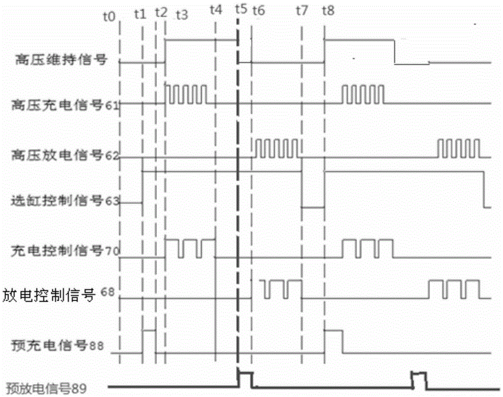
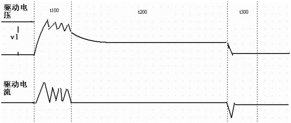
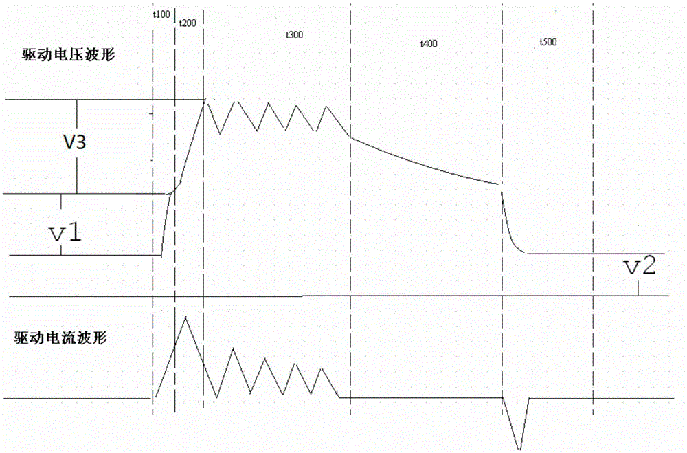
[0041] Such as figure 1 As shown: In order to effectively control the working process of the piezoelectric actuator 91, reduce the power consumption of the system, and reduce the influence of the dielectric loss on the fuel injector under complex working conditions, the present invention includes multiple piezoelectric actuators connected in parallel 91; the piezoelectric actuator 91 is connected to the actuator drive circuit module 3, and the actuator drive circuit module 3 includes a switch tube M2, a switch tube M3, and a switch tube M4 that is consistent with the number of the piezoelectric actuator 91; The drain of the switching tube M2 is connected to the output end of the high-voltage DCDC module 1 for providing the driving voltage required by the piezoelectric actuator 91, the source terminal of the switching tube M2 is connected to the drain terminal o...


PUM


Abstract

The invention relates to a driving piezoelectric injector device. A current feedback module monitors the current of a piezoelectric actuator in charging and discharging; a voltage feedback module monitors the voltage of the piezoelectric actuator in charging and is capable of regulating and controlling the high charging voltage and the discharging voltage of the piezoelectric actuator; an actuator medium consumption feedback control circuit regulates a charging threshold voltage; a capacitance gating compensation circuit compensates the capacitance of the piezoelectric actuator to prevent the medium consumption of the piezoelectric actuator influencing the work of the injector; an energy recycling circuit module recycles voltage from the voltage of the piezoelectric actuator and the transient high-voltage electric potential of an oil pump and is capable of pre-charging the piezoelectric actuator. The driving piezoelectric injector device is compact in structure, high in current control precision and capable of lowering the system consumption and improving the working stability and reliability of the injector under a complex working condition.

Description

technical field [0001] The invention relates to a circuit device, in particular to a device for driving a piezoelectric fuel injector, in particular to a drive circuit device for a piezoelectric crystal common rail system fuel injector, and belongs to the technical field of diesel engine common rail system drive . Background technique [0002] There are two types of fuel injectors in the common rail system: high-speed electromagnetic type and piezoelectric crystal type. Due to its special piezoelectric effect and capacitive effect, the piezoelectric ceramic actuator of piezoelectric crystal type can maintain A certain amount of elongation, so that the fuel injector can be opened to realize the fuel injection function. At present, for the injector of piezoelectric crystal common rail system, the power consumption of the system is relatively high, and the dielectric loss of piezoelectric crystal has an impact on the work of the injector, so it is difficult to ensure the work ...

Claims


Application Information

Patent Timeline
Patent Type & Authority Patents(China)
IPC IPC(8): H02J7/00
Inventor 高威宋国民张爱云曾伟寇伟俞谢斌沈妍
Owner CHINA FAW LIMITED WUXI FUEL INJECTIONEQUIP RES INST
Why Eureka
Try Eureka