Microgrid energy storage PCS control system and method

A control system and micro-grid technology, applied in the direction of AC network load balancing, etc., can solve the problems of low control gain, low power control precision, and control algorithm that is difficult to meet the requirements of stability and high precision at the same time, to achieve high power control accuracy, Effect of Improving Current Control Accuracy

Active Publication Date: 2019-02-22
NANJING GUODIAN NANZI POWER GRID AUTOMATION CO LTD
View PDF13 Cites 1 Cited by
  • Summary
  • Abstract
  • Description
  • Claims
  • Application Information

AI Technical Summary

Problems solved by technology

The user cannot independently set the output power parameters of each phase, and the power control parameters have not achieved decoupling control
[0006] 2. The power control accuracy is low
The control algorithm of the PCS control unit is difficult to meet the requirements of stability and high precision at the same time
The PI controller has strong stability but has the disadvantage of low control gain in the high frequency band; the proportional resonant controller (PR) has a very large gain at the fundamental frequency, and the low frequency band will cause inter-harmonic problems due to the fluctuation of the grid frequency, so It is difficult to use in the low frequency band, the quasi-proportional resonant controller will enlarge the cut-off frequency bandwidth of the PR controller, and the effect is poor in the high frequency band, and the parallel use of the proportional resonant controller (PR) and the quasi-proportional resonant controller can theoretically be realized The perfect effect of low gain in the low frequency band and high gain in the high frequency band, but it will sacrifice the phase angle margin of the control system, making it difficult to ensure the stability of the control system

Method used


Image

  • Microgrid energy storage PCS control system and method
  • Microgrid energy storage PCS control system and method
  • Microgrid energy storage PCS control system and method

Examples


Embodiment 1

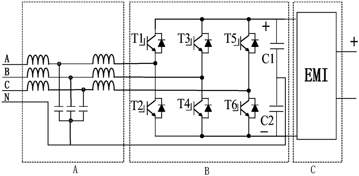
[0046] combine figure 1 with figure 2 As shown, the microgrid energy storage PCS control system of this embodiment includes: an LCL filter circuit, a three-phase bridge inverter circuit, a DC EMI filter circuit and a control module; the input terminal of the three-phase bridge inverter circuit passes through the DC EMI The filter circuit is connected to the battery, and the output terminal is connected to the three-phase power grid through the LCL filter circuit;

[0047] The output end of the three-phase bridge inverter circuit is respectively provided with a current sensor and a voltage sensor on the three-phase line, and the output ends of each current transformer and voltage sensor are respectively connected to the control module;

[0048] The control module receives the external three-phase command signal, and controls each switching device in the three-phase bridge inverter circuit according to the received command signal corresponding to each phase, and the voltage or...

Embodiment 2

[0064] This embodiment is a microgrid energy storage PCS control method, in which the input end and output end of the three-phase bridge inverter circuit are respectively connected to the storage battery and the three-phase power grid through a filter circuit; the method includes:

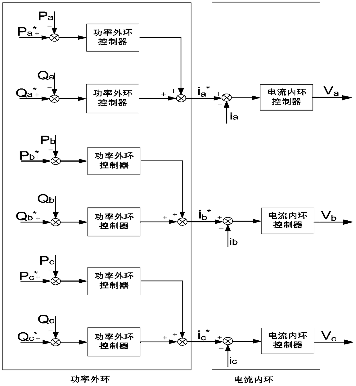
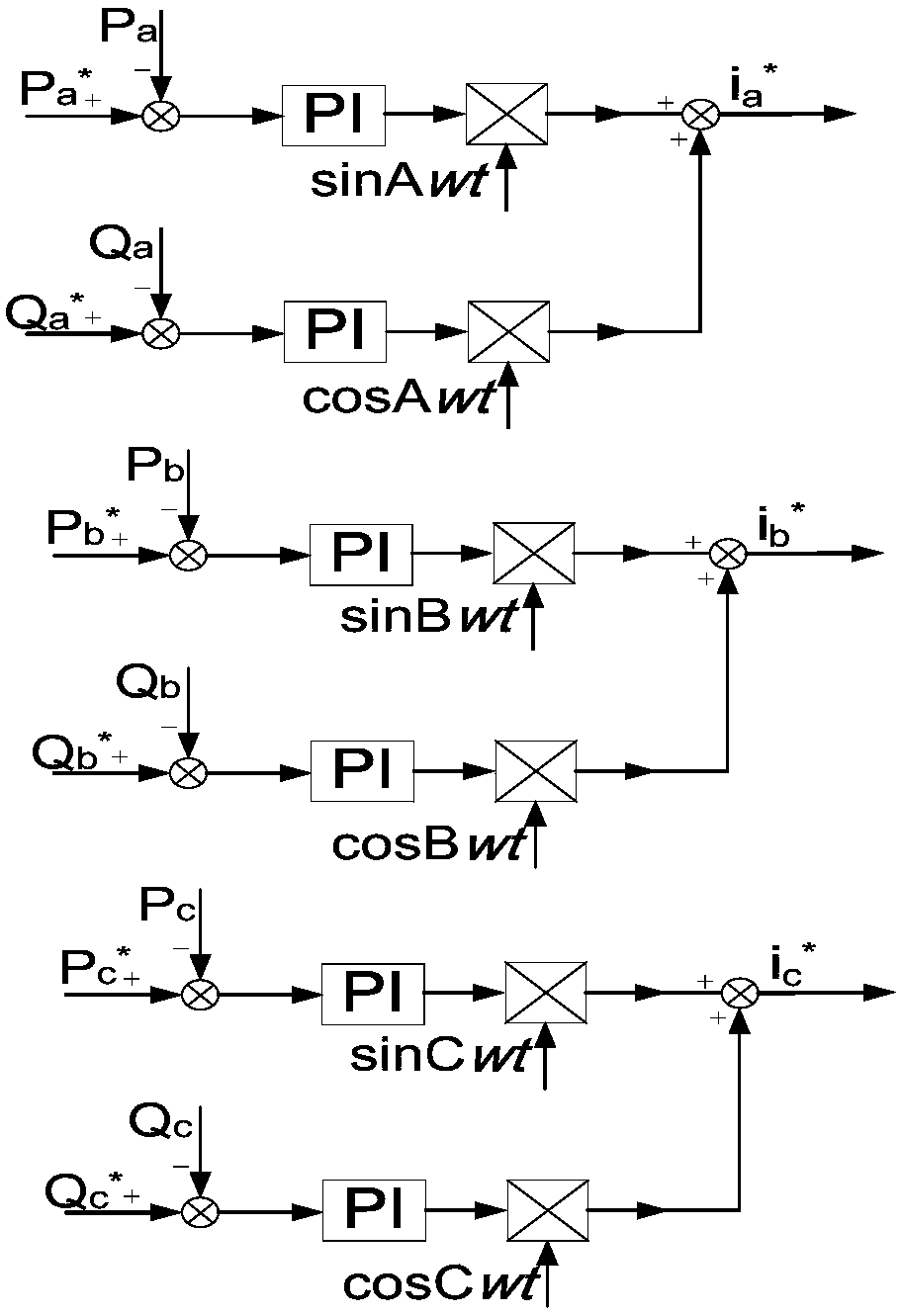
[0065] Obtaining an external three-phase command signal, where the external three-phase command signal includes a three-phase active power command signal and a three-phase reactive power command signal;

[0066] Obtain the voltage and current feedback values ​​at the output end of the three-phase bridge inverter circuit, and calculate the measured active / reactive power values ​​of each phase according to the voltage and current feedback values;

[0067] Obtain the phase angle value of the three phases of the power grid in real time;

[0068] For each phase, the difference between the active / reactive power command signal and the measured active / reactive power value is used as the input value, and th...


PUM


Abstract

The invention discloses a microgrid energy storage PCS control system and method. An input end of a three-phase bridge inverter circuit is connected to a storage battery through a direct current EMI filter circuit, and an output end is connected to a three-phase power grid through an LCL filter circuit; a current sensors and a voltage sensor are separately disposed on a three phase line of the output end of the three-phase bridge inverter circuit, and output ends of current transformers and the voltage sensor are separately connected to a control module; the control module receives an externalthree-phase command signal, and according to the received command signals corresponding to each of phases, and a voltage or a current feedback value input by a corresponding phase voltage sensor andcurrent sensor, turn-on or turn-off of each of switching devices in the three-phase bridge inverter circuit is controlled. The control module of the system and the method can achieve phase splitting control of microgrid energy storage, and the power control precision can be improved.

Description

technical field [0001] The invention relates to the technical field of microgrid energy storage control, in particular to a microgrid energy storage PCS control system and method. Background technique [0002] Compared with the traditional large power grid, distributed power generation has the characteristics of green and pollution-free, flexible installation location, high energy utilization rate, and reduced transmission loss energy of long lines. However, its own problems are gradually exposed, such as distributed power supply control is difficult, unstable, and costly. With the development of power electronics technology and modern control, a microgrid has emerged, which is composed of micro-sources, loads, control equipment, and energy storage equipment to form a controllable unit that provides electricity or heat to users. Compared with the large power grid, the micro-grid is closer to the load, without the need to build ultra-high voltage and long-distance power grid...

Claims


Application Information

Patent Timeline
Patent Type & Authority Applications(China)
IPC IPC(8): H02J3/32
CPCH02J3/32
Inventor 刘嘉程益德刘淮通
Owner NANJING GUODIAN NANZI POWER GRID AUTOMATION CO LTD
Why Eureka
Try Eureka