
Magnetic positioning system

a positioning system and magnetic field technology, applied in the direction of electrical/magnetically converting sensor output, navigation instruments, instruments, etc., can solve the problems of high cost of accurate ins sensor for passenger vehicles, inability to transmit simulated gnss signals, etc., and achieve accurate field models.

Active Publication Date: 2021-09-14
VITAL ALERT COMM
View PDF13 Cites 0 Cited by
  • Summary
  • Abstract
  • Description
  • Claims
  • Application Information

AI Technical Summary

Benefits of technology

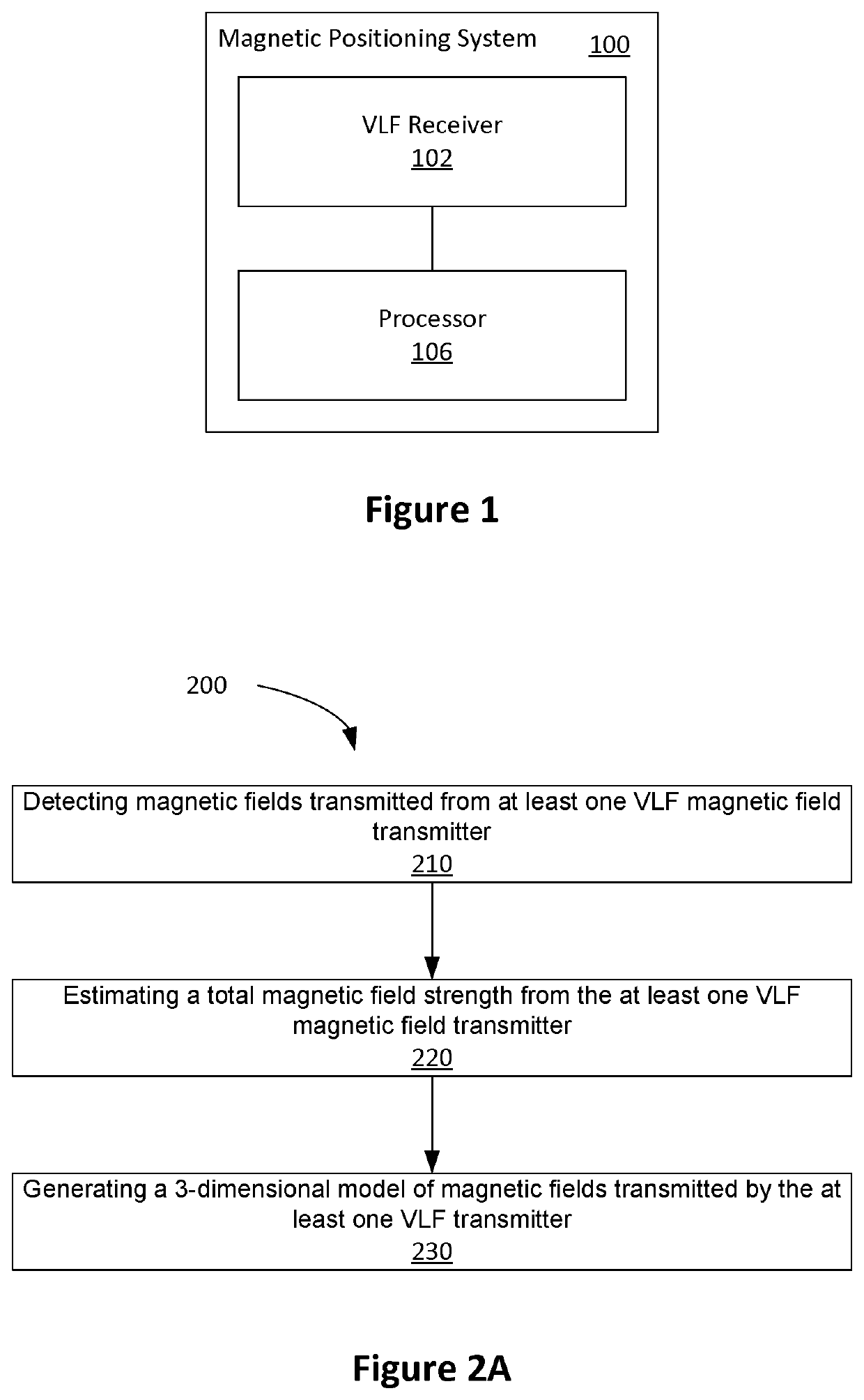
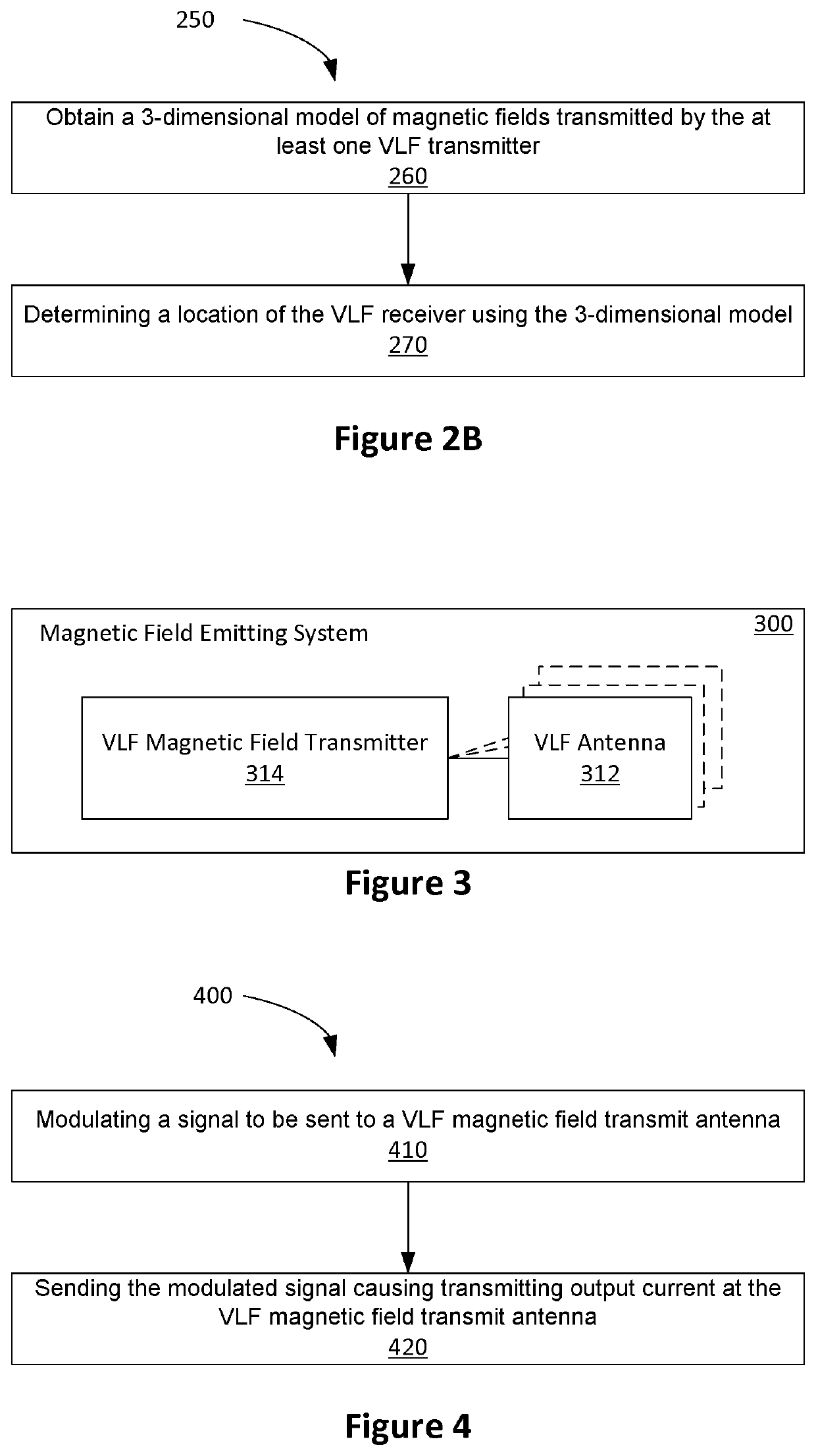
This patent describes a computer program that creates a model of an environment using a uniform cell size and assigned conductance values to model electrical properties. The program then sets up a transmitter to measure the magnetic fields in the environment and assigns initial conductivity values to major features of the structure. An FDTD simulation is then performed to create a model of the magnetic fields, which is optimized to match the observed field strengths. The technical effect is that this program enables the creation of accurate models of environments and the magnetic fields within them, which can aid in the design of various applications such as electric vehicles and wireless communication facilities.

Problems solved by technology

However, the transmission of simulated GNSS signals may not be practical in many cases as any signal leakage outside the obstructed area causes interference with the actual external GNSS signals.
These are electromechanical systems in which errors accumulate, making the cost of accurate INS sensor high for use in passenger vehicles.

Method used


Image

  • Magnetic positioning system
  • Magnetic positioning system
  • Magnetic positioning system

Examples


Embodiment Construction

lass="d_n">[0043]Embodiments described herein may provide a magnetic positioning system for environments that constructed using, or otherwise include, conducting material (e.g., magnesium phosphosilicate cement MPSCM, or steel reinforced concrete). Such environments include underground mines, tunnels and parking structures.

[0044]Systems based on using radio frequency (RF) waveforms, such as Wi-Fi, or Bluetooth, have been proposed. In such systems, a receiver determines its location based on the signal level or direction of arrival of the signals from a number of transmitters set up at known fixed locations. However, RF based methods are degraded by the presence of multipath signals created by the signal from the local transmitter undergoing multiple reflections from the ground and other conducting structures in the environment. Reinforced concrete, which is widely used in the construction of parking garages and underpasses, has a relatively high conductivity property, and thus acts ...


PUM

PropertyMeasurementUnit
frequenciesaaaaaaaaaa
frequencyaaaaaaaaaa
conductivityaaaaaaaaaa

Abstract

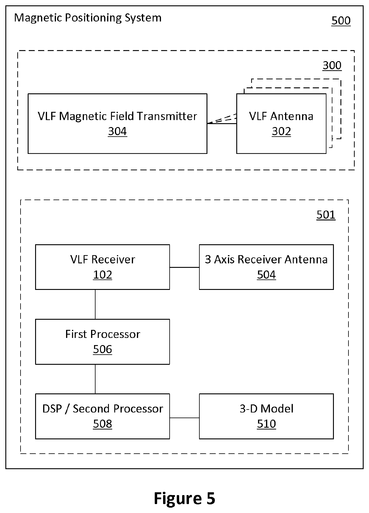
Embodiments described herein relate to a magnetic positioning system and method that allows the position of a receiver to be determined in environments containing conducting material such as concrete. A number of transmitters create modulated magnetic fields which are distorted as they propagate through the conducting materials. A finite difference time domain (FDTD) simulation of the environment is used to generate an accurate model of the fields within the environment. A receiver is used to measure the field strength of each transmitter. The receiver position is determined by evaluating the misfit between the received fields and the values in the FDTD model.

Description

CROSS REFERENCE TO RELATED APPLICATIONS[0001]This application is national stage entry of PCT / CA2017 / 051554 filed Dec. 20, 2017, which claims the benefit of and priority to U.S. provisional application No. 62 / 437,413 filed Dec. 21, 2016, the contents of all of which are hereby incorporated by reference.FIELD[0002]Embodiments described herein generally relate to the field of very low frequency (VLF) positioning systems, and more specifically to VLF positioning in an environment constructed with, or otherwise including, conducting materials.INTRODUCTION[0003]Accurate determination of vehicle location and orientation is useful in the context of autonomous vehicles, for example. In areas with access to areas of open sky, vehicles can receive signals from satellite based global navigation satellite systems (GNSS) to determine their location and direction of travel. Such coverage is available world-wide.[0004]There are types of environments that vehicles have to navigate, such as undergrou...

Claims


Application Information

Patent Timeline
Patent Type & Authority Patents(United States)
IPC IPC(8): G01R33/10G01C21/20G01D5/12G01S1/70
CPCG01C21/206G01D5/12G01R33/10G01S1/7034G01S1/7038G01S2201/01G01B7/004G01S5/16G01S5/0205
Inventor ROPER, MICHAEL JAMESKWASNIOK, PETERRALCHENKO, MAXIM
Owner VITAL ALERT COMM
Learn More