

Production logs from distributed acoustic sensors
a technology of distributed acoustic sensors and production logs, which is applied in the field of distributed fiber optic sensing, can solve the problems of difficulty in assessing the effectiveness of various well treatment strategies during completion or after production, and achieve the effect of increasing the resolution of data
- Summary
- Abstract
- Description
- Claims
- Application Information
AI Technical Summary
Benefits of technology
Problems solved by technology
Method used
Image

Examples
example 1
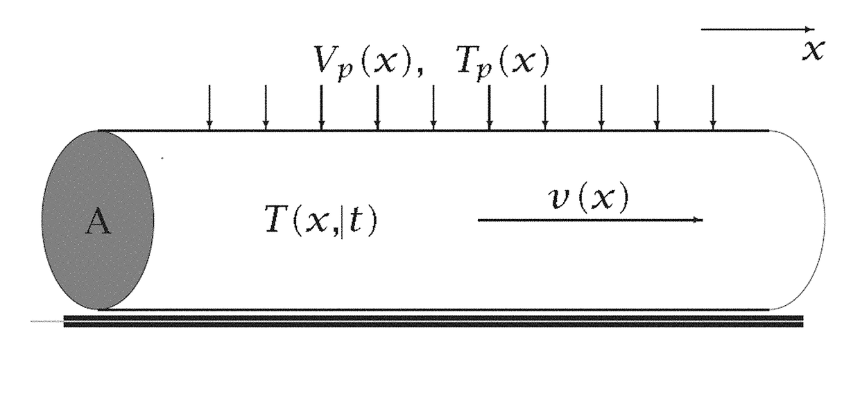
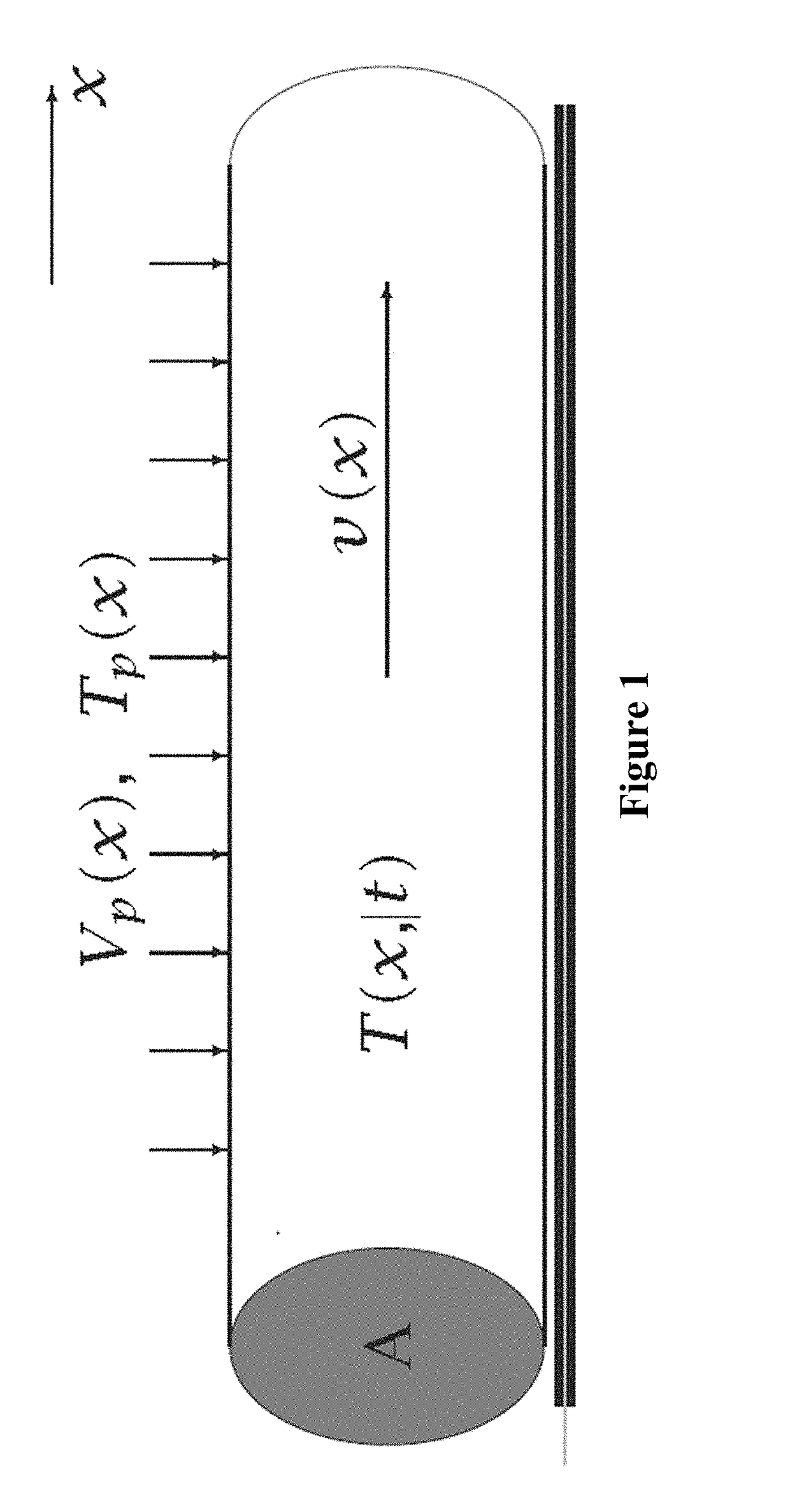
[0097]FIG. 1 illustrates a buried horizontal oil well during production. The well has a cross-sectional area of A, and is closed off at its toe-end. The other end eventually reaches the surface, where a throttling valve controls the total production from the well. This total production is denoted by P(t), which is a function of time, t. As shown in FIG. 1, a horizontal section of a well with an attached tube containing an optical fiber, and production perforation points indicated by vertical arrows. The fluid flow vector v(x) points in the positive x-axis.
[0098]An optical fiber encased in a gel-filled metallic tube is either fastened to the outside of the well casing (as shown) or inserted within it, so that it is in close thermal contact with the fluids inside the well. This fiber is connected to a DAS interrogation unit, such as is described by Cekorich and Bush (2004). This unit measures small expansions and contractions of the fiber by sending laser pulses down the fiber and rec...
example 2
[0104]To obtain a more quantitative measure of fluid flow, we denote the temperature of the fluid inside the well at position x and time t as T(x, t). A detailed analysis of the heat flow of this problem shows that recorded DAS signal D(x, t), which is proportional to the time derivative of the temperature, is given by Equation 1:
βD=∂T∂t=-υ∂T∂x+VpA(Tp-T)+KcA(Tf-T)+Kf∂2T∂x2
[0105]Where β is the coefficient of proportionality between the DAS response and the time derivative of temperature. It is related to the thermal expansion coefficient of the glass fiber and the sensitivity of the DAS instrument. Knowing its value is not necessary to determine the flow rates.
[0106]The terms on the right side of this equation constitute, in order, the following contributions to the DAS response:[0107]Fluid flow—When a fluid that has a non-uniform temperature distribution flows along a well, the temperature at a fixed point along that well will change at a rate given by to the velocity of the fluid t...
example 3
[0123]In order to improve resolution, a large time window may be used to conduct the analysis. In order to accommodate the larger time window, the linear relation between time and position (i.e. Eq. 7) cannot be assumed. Calculating the nonlinear relationship between time and position by solving Eq. 5 without assuming time is sufficiently small or that fluid temperature is sufficiently smooth. First define the new variable U(x,t)=v(x)D(x, t) and set Kc=0, Eq. (5) becomes Equation 9:
∂U∂t+υ(x)∂U∂x=0
[0124]Eq. 9 is a first-order, linear, homogenous, partial differential equation. Every solution of this equation must satisfy its characteristic Equation 10:
υ(x)=-dxdt
which is easily seen by substituting Eq. (10) into Eq. (9). Multiplying by dt and integrating, we obtain Equation 11:
t=-∫dξυ(ξ)+C=-∫S(ξ)dξ+C
where s(ξ)=1 / v(ξ) is the fluid slowness function, which is the reciprocal of velocity.
[0125]The general analytic solution to Eq. (9) is Equation 12:
U(x, t)=F(C)=F[t+∫s(ξ)dξ]
where F(r) is a...
PUM
 Abstract
Description
Claims
Application Information