

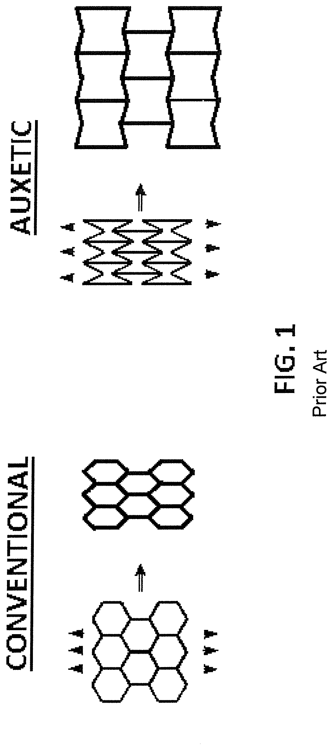
Auxetic bi-stable structure
a bi-stable structure and shell technology, applied in the direction of machines/engines, mechanical equipment, transportation and packaging, etc., can solve the problems of sudden non-controlled shape change and unsatisfactory deformation, and achieve the effect of positive poisson ratio, simplified explanation, and stiffening effect of the shell
- Summary
- Abstract
- Description
- Claims
- Application Information
AI Technical Summary
Benefits of technology
Problems solved by technology
Method used
Image

Examples
Embodiment Construction
[0046]FIGS. 9 to 18b disclose several embodiments, most of them implemented in a passive bi-state aerodynamic auxiliary power unit (APU) intake, cabin air system intake, auxiliary ventilation intake or other system intake, that could be placed on the nacelle, fuselage, belly fairing, tails surfaces, or other surface of an aircraft.
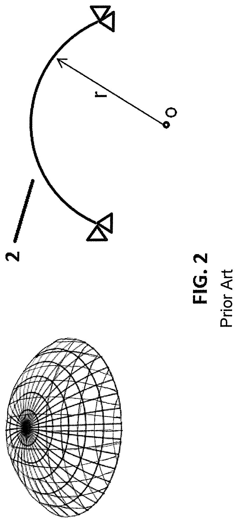
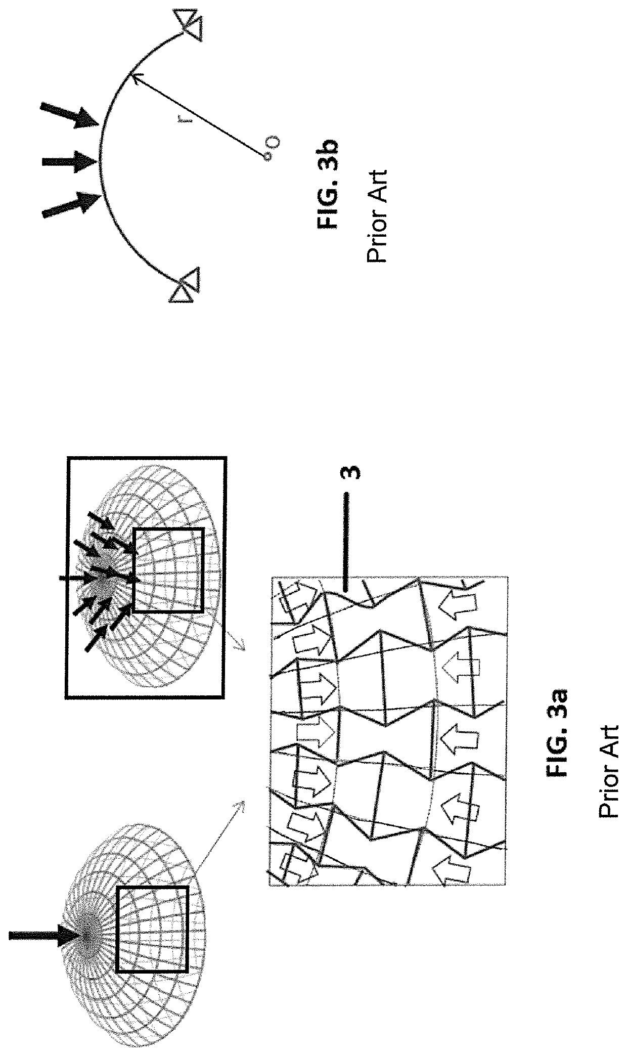
[0047]Particularly, the auxetic curved shell (2) and the rigid element (1) could be joined such that the movement of the part of the surface of the auxetic curved shell (2) joined to the rigid element (1) is restricted in one direction in a Cartesian coordinate system. In another alternative, the auxetic curved shell (2) and the rigid element (1) are joined such that the movement of the part of the surface of the auxetic curved shell (2) joined to the rigid element (1) is restricted in two directions in a Cartesian coordinate system or even restricted in two directions and in a momentum perpendicular to said two directions in a Cartesian coordinate system....
PUM
 Abstract
Description
Claims
Application Information