Compact antenna device

a technology of antenna device and antenna, which is applied in the direction of antenna earthing, instruments, antennas, etc., can solve the problems of insufficient complete satisfaction of the device from the prior art, inability to fully satisfy the radiation pattern of the antenna, and inability to meet the radiation pattern of the devi

Active Publication Date: 2021-09-28
COMMISSARIAT A LENERGIE ATOMIQUE ET AUX ENERGIES ALTERNATIVES
View PDF11 Cites 0 Cited by
  • Summary
  • Abstract
  • Description
  • Claims
  • Application Information

AI Technical Summary

Benefits of technology

[0021]Such a device according to the invention is thus able to remain compact while at the same time keeping maximum gain in the azimuthal plane (i.e. the plane defined by the ground plane), and to do so by virtue of the first and second strands of the or each dipole antenna, which extend on either side of the ground plane. Specifically, such a geometrical configuration of the strands makes it possible to limit the disturbance of the radiation pattern of the corresponding dipole antenna by the ground plane, and to do so in spite of the spatial finiteness of the ground plane.
[0051]One advantage that is provided is thus that of achieving an aperture angle of 45° for the beam if the four pairs of peripheral dipole antennas are distributed uniformly around the central dipole antenna, and with matched load impedances within the control circuit.

Problems solved by technology

Such a device from the prior art is compact.
The spatial finiteness of the ground plane (i.e. of finite dimension) exhibits a drawback with regard to the radiation pattern of the antenna.
However, such a device from the prior art is not completely satisfactory in that introducing the skirt considerably increased the size of the antenna (by a factor of 2 for the thickness).

Method used


Image

  • Compact antenna device
  • Compact antenna device
  • Compact antenna device

Examples


Embodiment Construction

[0066]Elements that are identical or provide the same function will carry the same references for the various embodiments, for the sake of simplicity.

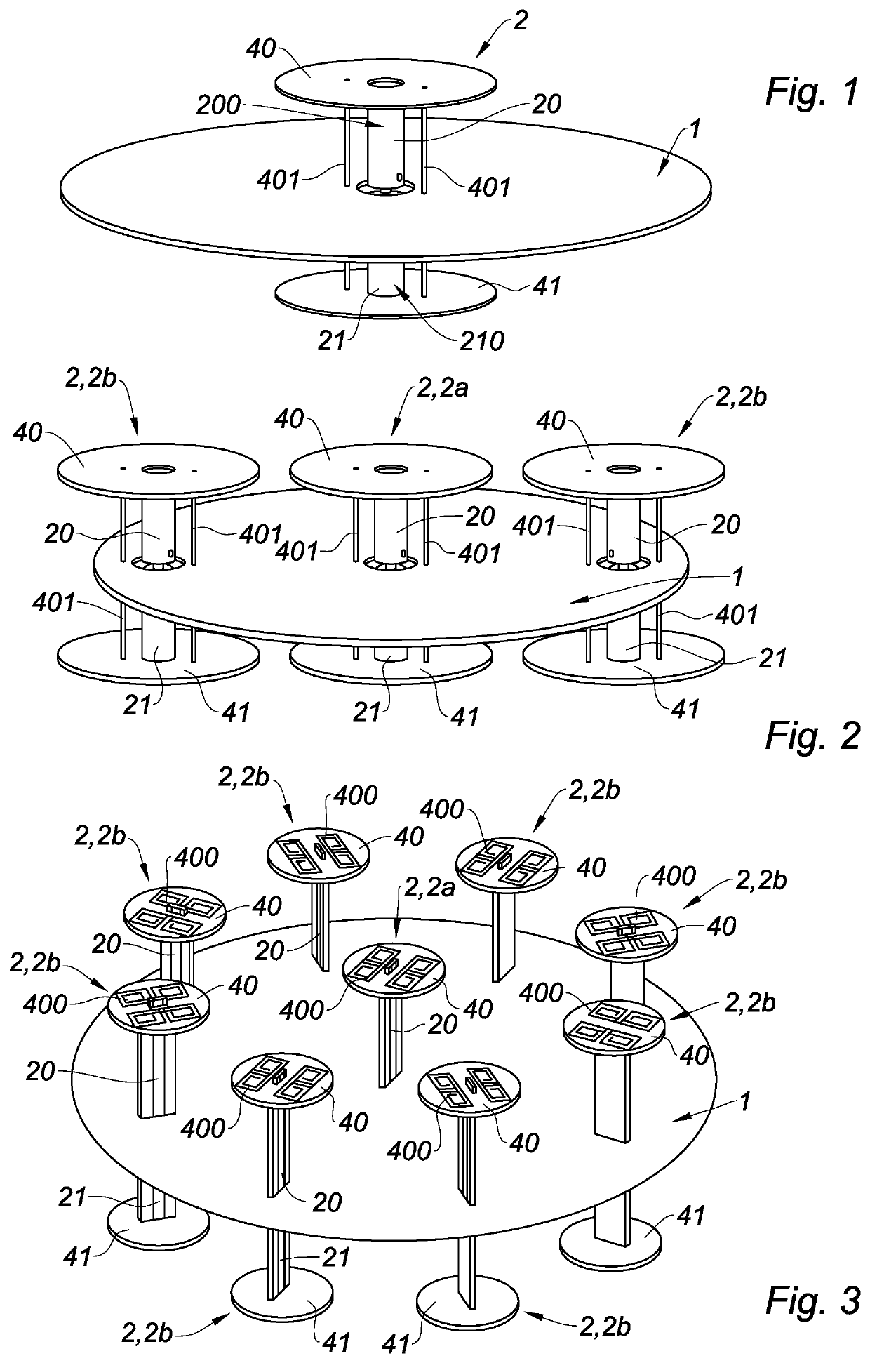
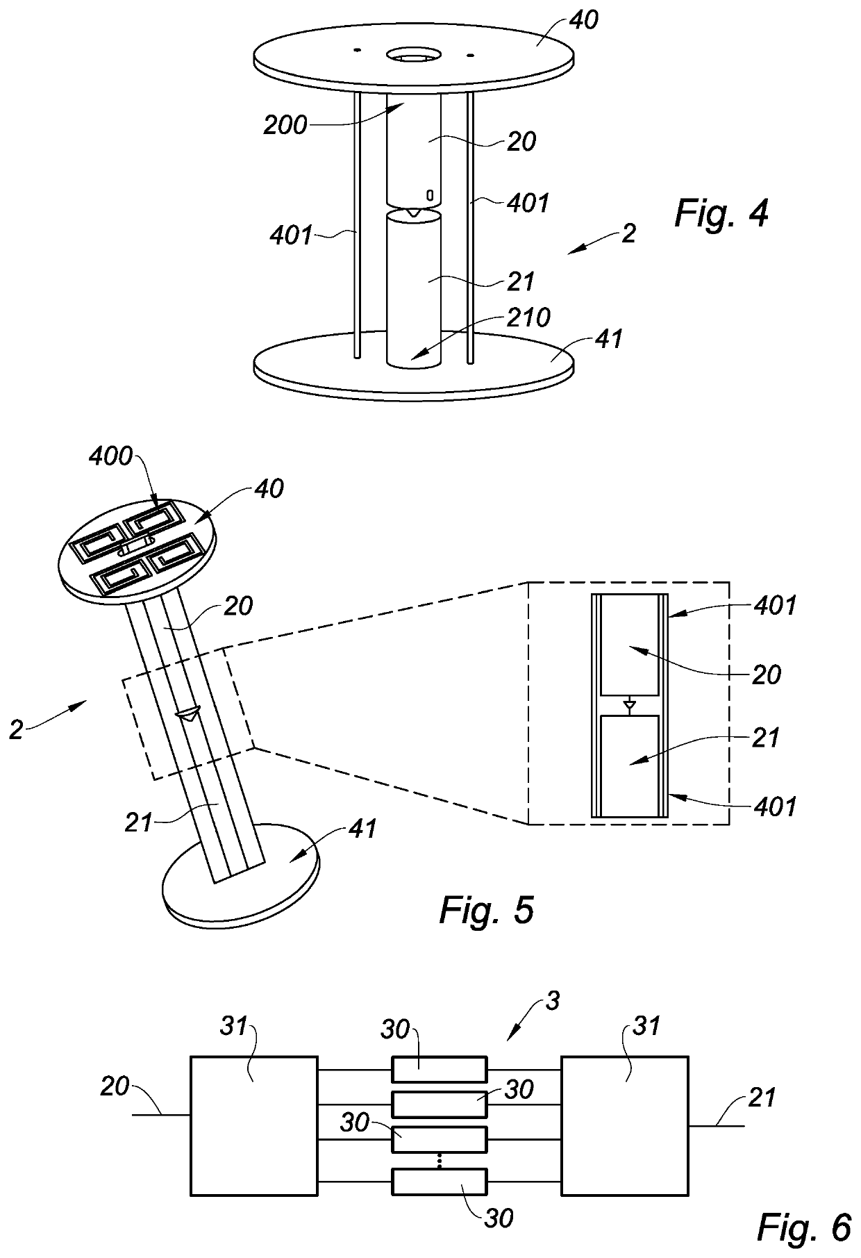
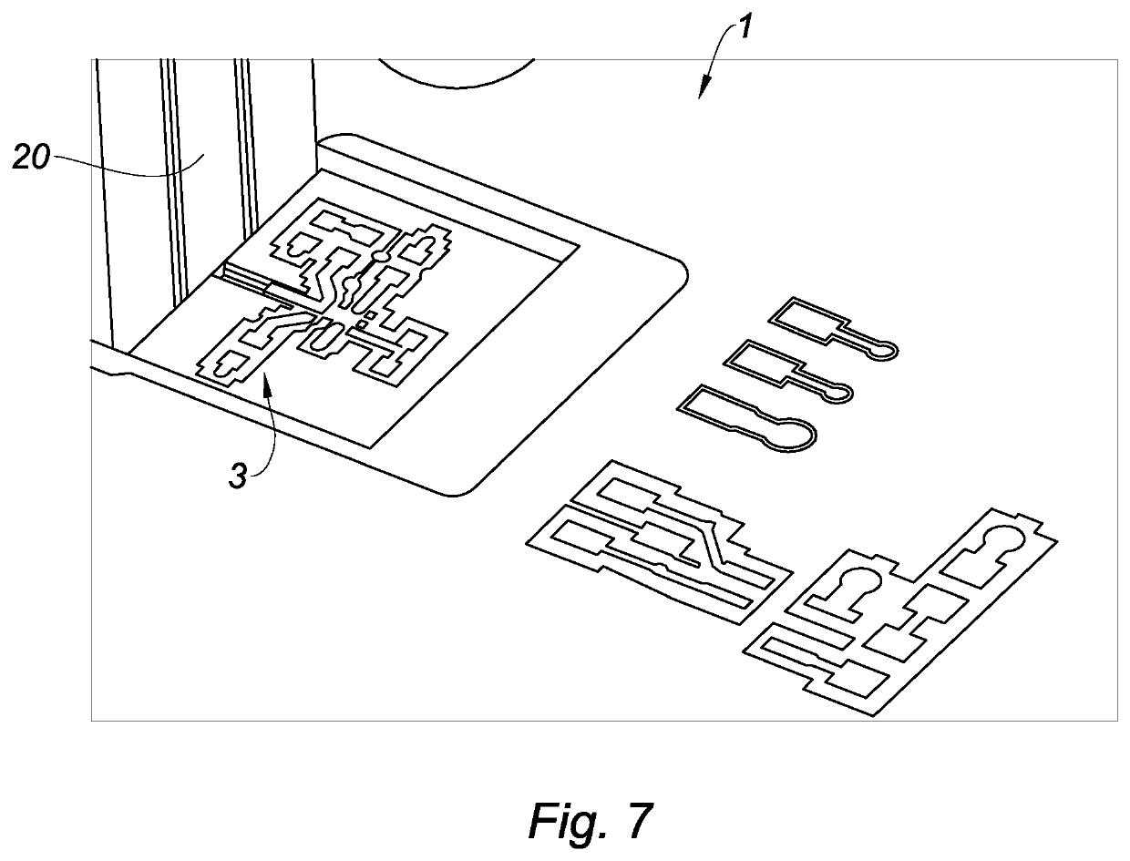
[0067]One subject of the invention is an antenna device, having:[0068]a ground plane 1 at floating potential;[0069]at least one dipole antenna 2, extending through the ground plane 1, and comprising first and second strands 20, 21 extending on either side of the ground plane 1;[0070]a control circuit 3, arranged on the ground plane 1 in order to control the or each dipole antenna 2.

Ground Plane

[0071]The ground plane 1 may be formed from a metal material, such as copper. The ground plane 1 may be circular in shape, for example with a diameter λ / 2, where λ is the operating wavelength of the antenna. However, the diameter of the ground plane 1 may be less than λ / 2. By way of nonlimiting example, in the case of an RFID spatial filtering application in the UHF band (around 868 MHz), the diameter of the ground plane 1 is 18 cm.

[0072]However,...


PUM


Abstract

A compact antenna device has a ground plane at floating potential and at least one dipole antenna extending through the ground plane. The at least one dipole antenna has first and second strands extending on either side of the ground plane. A control circuit is arranged on the ground plane in order to control the at least one dipole antenna.

Description

TECHNICAL FIELD[0001]The invention relates to the technical field of compact antenna devices. The antenna device may form a directional antenna with beam offsetting, or else form a reconfigurable antenna.Definitions[0002]“Compact” is understood to mean that the maximum characteristic dimension of the antenna device is less than or equal to λ / 2, where λ is the operating wavelength of the device.[0003]“Directional” is understood to mean the capability of an antenna to concentrate the radiated energy within a solid angle or in a specific direction. This capability, expressed in dBi (decibels relative to isotropic), is defined as being the maximum value of the ratio between the power radiated per solid angle unit and the average radiated power over all directions in space.[0004]“Super-directional” is understood to mean that the antenna has a directivity that exceeds a reference limit, such as the maximum theoretical Harrington limit.[0005]“Beam offsetting” is understood to mean that the...

Claims


Application Information

Patent Timeline
Patent Type & Authority Patents(United States)
IPC IPC(8): H01Q9/28H01Q1/48H01Q3/26H01Q5/48G06K19/077
CPCH01Q9/285H01Q1/48H01Q3/2605G06K19/07786H01Q5/48H01Q9/18H01Q9/28H01Q19/108H01Q25/005
Inventor BATEL, LOTFICLEMENTE, ANTONIODELAVEAUD, CHRISTOPHE
Owner COMMISSARIAT A LENERGIE ATOMIQUE ET AUX ENERGIES ALTERNATIVES
Why Eureka
Try Eureka