Multifunctional stapler

a multi-functional, stapler technology, applied in the field of hand tools, can solve the problems of affecting the stapling effect, inconvenient operation for users, and relatively high production cost of processing and assembly, and achieve the effect of stapling effect, simple structure and better striking

Active Publication Date: 2021-10-12
HANGZHOU GREAT STAR IND CO LTD +1
View PDF22 Cites 0 Cited by
  • Summary
  • Abstract
  • Description
  • Claims
  • Application Information

AI Technical Summary

Benefits of technology

[0005]An objective of the present invention is to provide a multifunctional stapler which solves the problems existing in the prior art of poor stapling effects, complicate structures, relatively high production costs and inconvenient operations.
[0025]The present invention provides a multifunctional stapler, capable of adjusting a depth of the staple feeding groove, such that the staples with different widths may be stably positioned in the staple feeding groove, thus being struck out, so as to realize stapling effects. The present invention may further adjust the strike force according to the thickness of the object to be stapled, thereby realizing better striking effects. The multifunctional stapler according to the present invention has a simple structure, a relatively low production cost, convenient operations, and a wide application range, can be used for striking staples of various specifications and shapes, such as T-shaped staples, ‘-’-shaped staples, U-shaped staples, or barbed staples with different widths and heights.

Problems solved by technology

It has the disadvantages that the sliding member in this design solution has to be firstly manipulated to slide up and down, and then a positioning member on the sliding member is operated to implement positioning, so that this stapler needs two operations to achieve the positioning effects, making it inconvenient for a user to operate.
Meanwhile, this design solution also has the problem of an over-complicated structure, in that the positioning structure of the sliding member is too complicated, and the production costs of processing and assembling are relatively high.
It has the disadvantages that there is only such a structure for adjusting the distance between the adjusting member and the staple box that the stapler may be suitable for the staples with different widths (or thicknesses), but not provided with a solution for adjusting a strike force of a striking member, so that regardless of a thickness of an object to be stapled, the striking member strikes the staples with the same strike force.
Once the object to be stapled is relatively thick, the staples cannot penetrate through all the objects to be stapled, which may affect the stapling effects.
Meanwhile, a runner structure is required in this design solution, the requirement for the processing and assembling accuracy is high, and the production cost is relatively high.

Method used


Image

  • Multifunctional stapler
  • Multifunctional stapler
  • Multifunctional stapler

Examples


Embodiment Construction

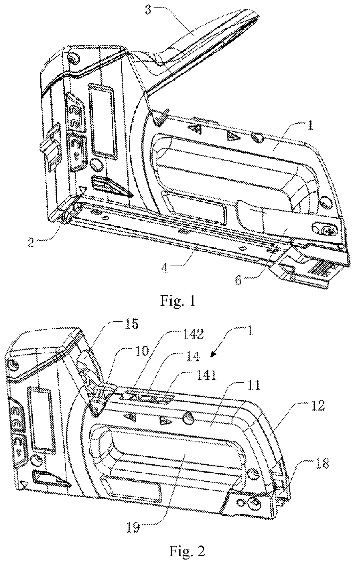
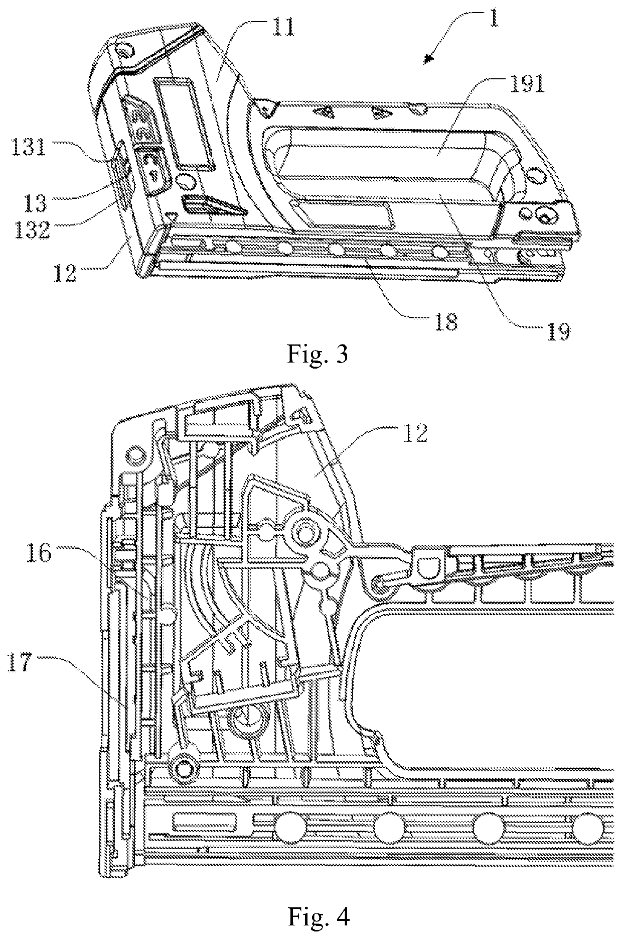
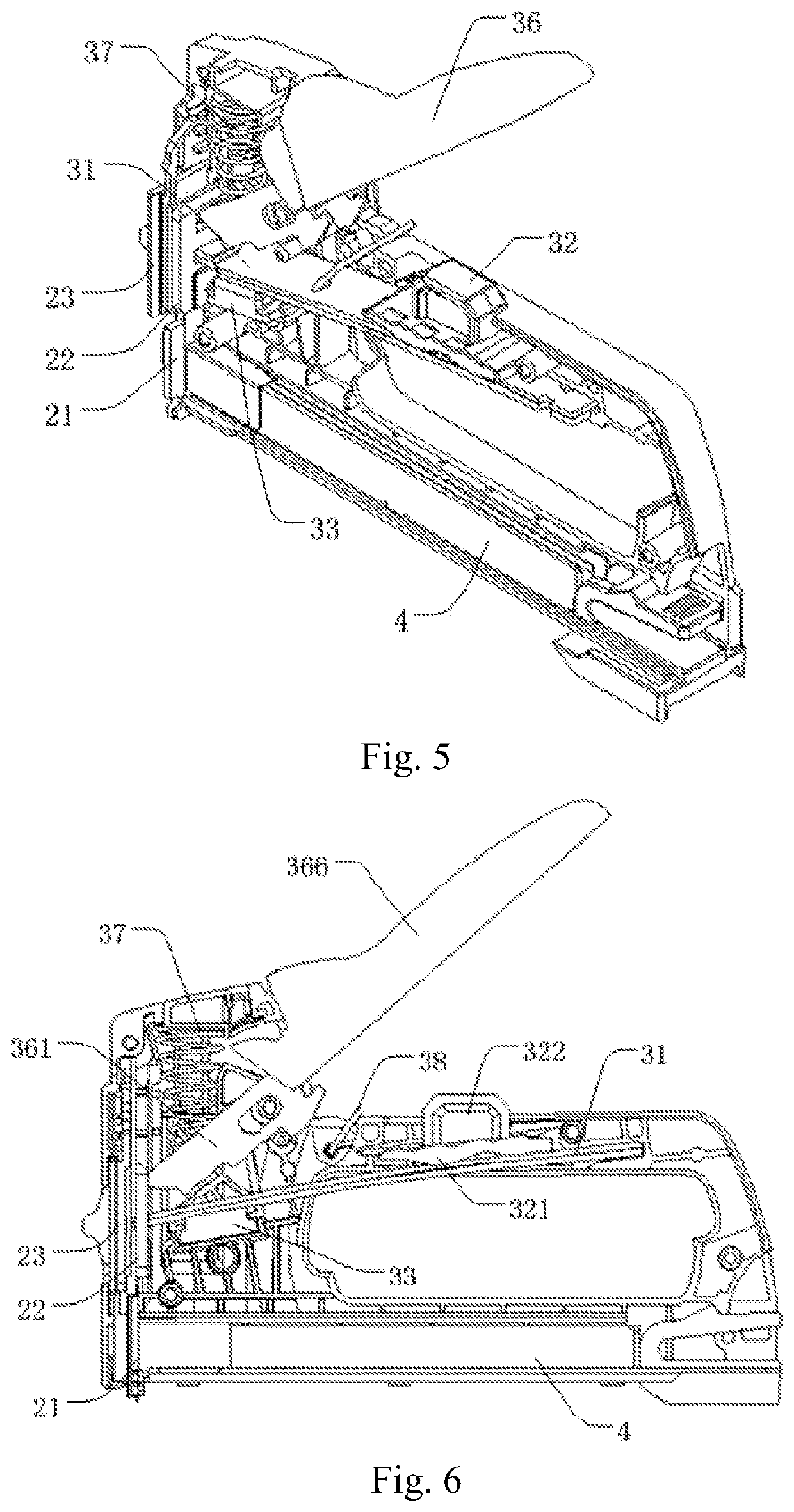
[0062]The present invention will be described more fully for those skilled in the art hereinafter with reference to the accompanying drawings by introducing one of the preferable embodiments of the present invention, for the purpose of clarity and better understanding of the techniques. This invention may be embodied in various different forms and the invention should not be construed as being limited to the embodiments set forth herein.

[0063]In the accompanying drawings elements with identical structure are marked with the same reference numerals, and like elements with similar structure or function are marked throughout with like reference numerals, respectively. The dimension and thickness of each of the elements in the accompanying drawings are arbitrarily shown, and the invention does not define the dimension and thickness of each element. Certain elements may be shown somewhat exaggerated in thickness in the interest of clarity.

[0064]Directional relative terms mentioned in the...


PUM


Abstract

The present invention provides a multifunctional stapler including a housing, a nailing portion arranged at a front end of the housing, and a toggling device, a part of which being arranged inside the housing and a part of which extending to the outside of the housing. The nailing portion comprises: a staple feeding member arranged at a front end of the bottom of the housing, a staple feeding groove arranged on the surface at one side of the staple feeding member for receiving staples, a striking member, a part of which being inserted into the staple feeding groove, the toggling device controlling the striking member to strike the staples, and an adjusting device, a part of which being arranged outside the housing, for adjusting a depth of the staple feeding groove.

Description

FIELD OF THE INVENTION[0001]The present invention relates to a hand tool, and in particular, to a multifunctional stapler.DESCRIPTION OF THE PRIOR ART[0002]The PCT patent WO 2005 / 102613A1, entitled “Stapler With Adapter”, discloses a stapler suitable for four specifications of staples (a T-shaped staple, a U-shaped staple, a barbed staple, a ‘-’-shaped staple), which controls a sliding member to move up and down, while driving an adjusting member to contact staples selectively, so as to achieve the purpose that the stapler can be applied to staples of different thicknesses. It has the disadvantages that the sliding member in this design solution has to be firstly manipulated to slide up and down, and then a positioning member on the sliding member is operated to implement positioning, so that this stapler needs two operations to achieve the positioning effects, making it inconvenient for a user to operate. Meanwhile, this design solution also has the problem of an over-complicated s...

Claims


Application Information

Patent Timeline
Patent Type & Authority Patents(United States)
IPC IPC(8): B25C5/11B25C5/16
CPCB25C5/11B25C5/162B25C5/1606B25C5/1641B25C5/0285
Inventor WANG, WEIYI
Owner HANGZHOU GREAT STAR IND CO LTD
Why Eureka
Try Eureka