
Vehicle and battery pack

a battery pack and battery technology, applied in the field of vehicles and battery packs, can solve the problems of poor carriability, unstable holding battery packs, difficult to remove the arm from the battery pack and return it to the carrier device after, etc., to achieve the effect of facilitating ensuring a space and affecting the performance of the battery uni

Active Publication Date: 2021-10-19
TOYOTA JIDOSHA KK
View PDF16 Cites 0 Cited by
  • Summary
  • Abstract
  • Description
  • Claims
  • Application Information

AI Technical Summary

Benefits of technology

[0006]An opening provided in the upper portion of the battery case can thus be used to hang and thus hold the battery pack. Hanging and thus holding the battery pack allows the held battery pack's center of gravity to be below the portion of the battery pack supported by the holding hook and thus helps to stabilize the held battery pack in posture. Furthermore, when mounting the battery pack in the recess of the floor panel, arranging the opening provided in the upper portion of the battery case to assume a position above the recess eliminates the necessity of providing a space in the recess for pulling out the arm.
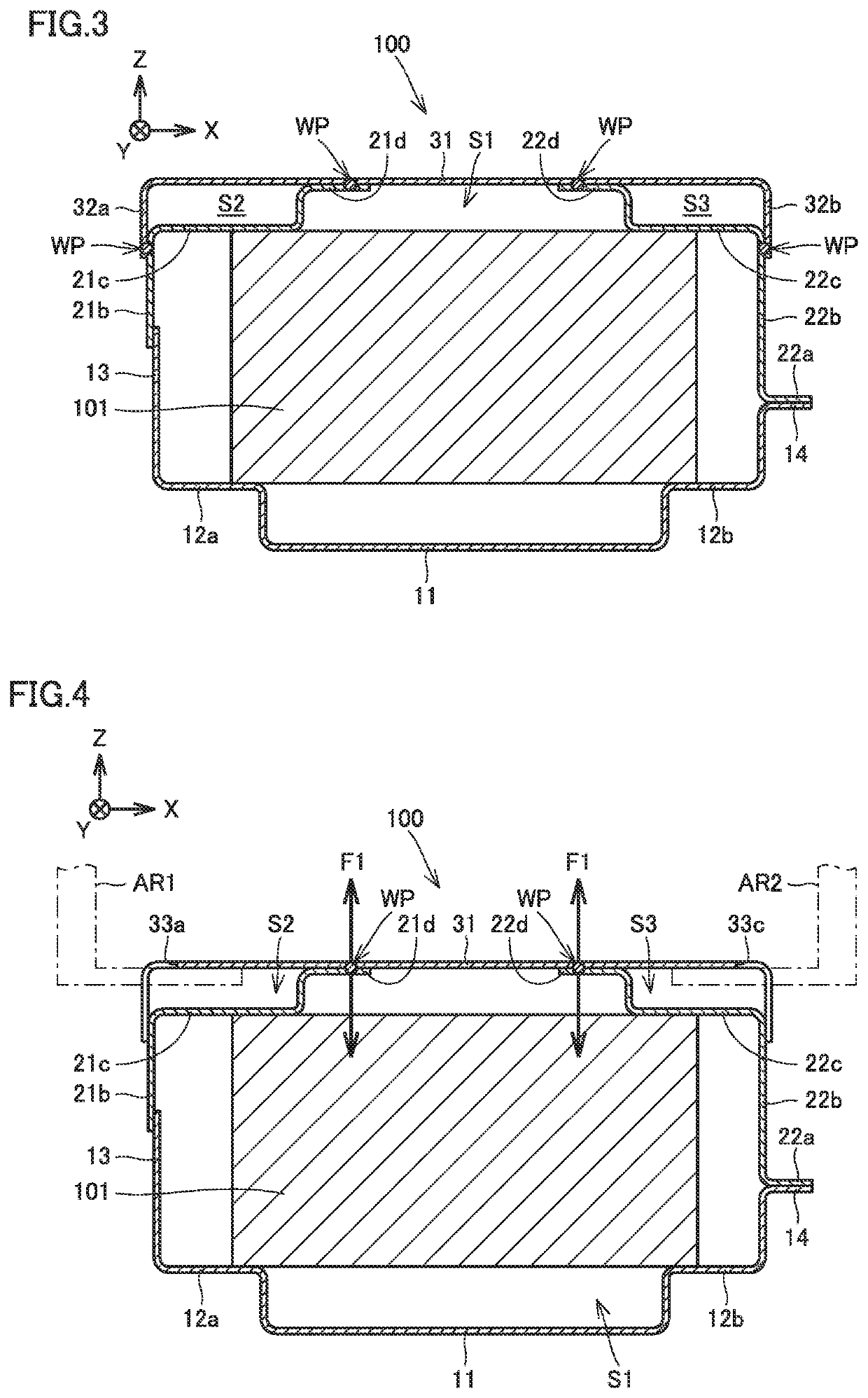
[0025]When the battery case includes a first space to receive the holding hook through the opening and a second space accommodating the battery unit therein it is preferable that the first space and the second space be not in communication with each other. When the holding hook is inserted into the first space, a foreign matter and water easily enter the first space together with external air. In the above configuration, the first space and the second space are not in communication with each other, and the foreign matter or water having entered the first space does not enter the second space. This prevents the foreign matter and water from affecting and thus impairing the performance of the battery unit accommodated in the second space.

Problems solved by technology

In such a method, however, the held battery pack has its center of gravity higher in level than the portion thereof supported by the arm, and the held battery pack is unstable in posture and thus poor in carriability.
In addition, in such a method, if there is not enough space around the mounted battery pack, it is difficult to remove the arm from the battery pack and return it to the carrier device after the battery pack has been mounted.
However, such an opening may reduce the battery case in strength against a force exerted from above the battery pack.
Furthermore, reinforcing the battery case per se leads to an increased cost.
Since the frame member is supported by the vehicular body, the load exerted to the frame member is transmitted to the vehicular body and is not easily transmitted to the opening.
However, when the first to fourth openings are all arranged under a single seat mounting member, the first to fourth openings are positionally limited to a location under the seat mounting member, and it is thus difficult to arrange the first to fourth openings to be distant from one another.
This prevents the foreign matter and water from affecting and thus impairing the performance of the battery unit accommodated in the second space.

Method used


Image

  • Vehicle and battery pack
  • Vehicle and battery pack
  • Vehicle and battery pack

Examples


Embodiment Construction

[0039]The present disclosure will now be described in embodiments hereinafter in detail with reference to the drawings. In the figures, identical or corresponding components are identically denoted and will not be described repeatedly.

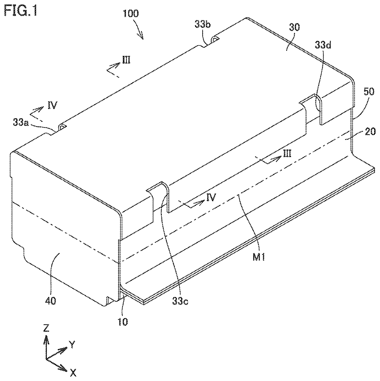
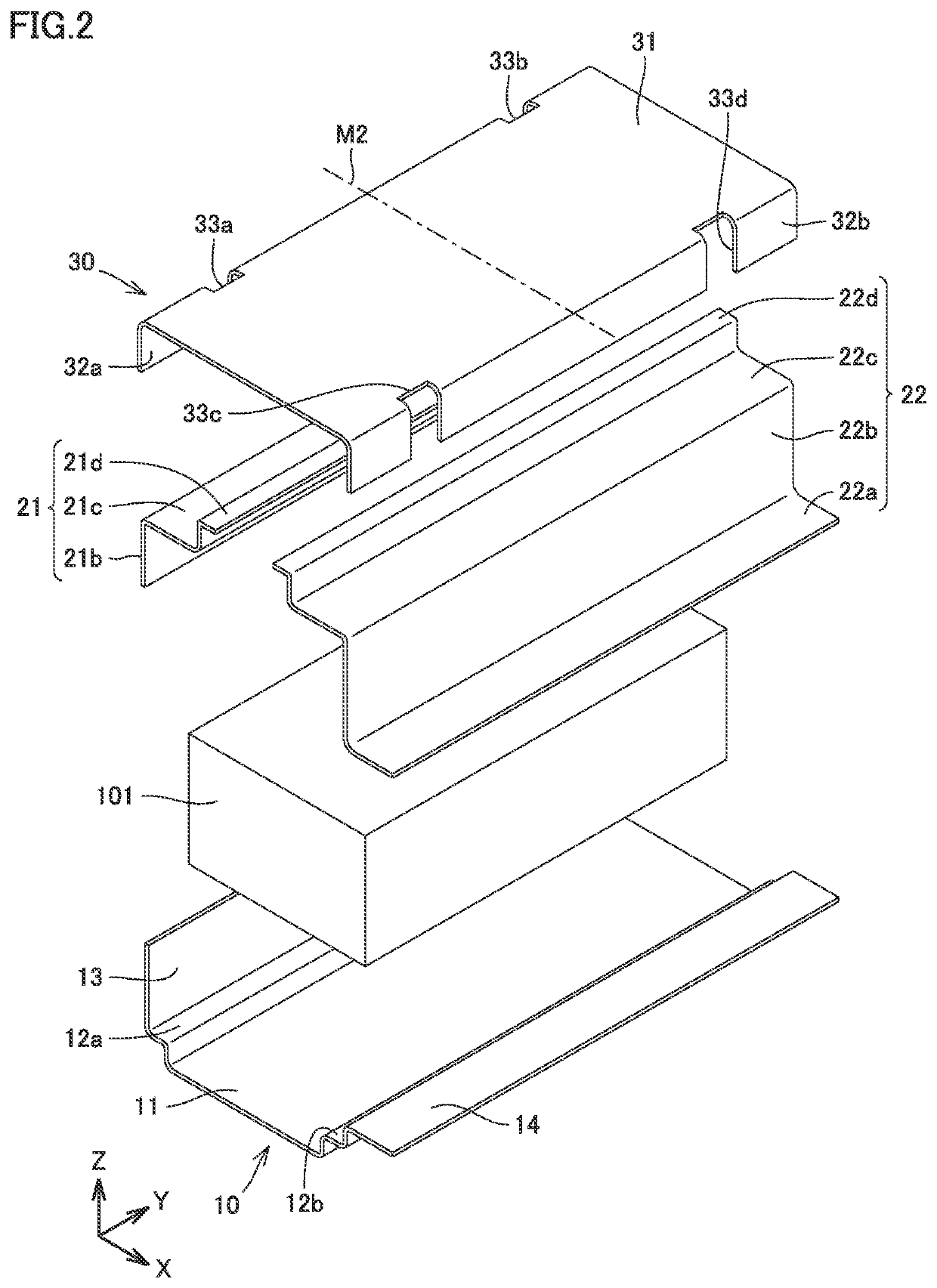
[0040]A configuration of a battery pack according to an embodiment of the present disclosure will schematically be described with reference to FIGS. 1 and 2. Each figure indicates mutually orthogonal X, Y and Z axes, and the X axis represents the battery pack's widthwise direction, the Y axis represents the battery pack's lengthwise direction, and the Z axis represents the battery pack's heightwise direction. In the following, one direction indicated by an arrow of each of the X, Y and Z axes is represented with “+” added thereto, and the opposite direction is represented with “−” added thereto. Further, the +Z direction may be referred to as “upper” or the like and the −Z direction may referred to as “lower” or the like.

[0041]FIG. 1 is a perspective v...


PUM

PropertyMeasurementUnit
gravityaaaaaaaaaa
strengthaaaaaaaaaa
forceaaaaaaaaaa

Abstract

A vehicle includes a battery pack, seats, and seat rails. The battery pack has a battery case and a battery unit accommodated in the battery case. The seat rails are frame members disposed over the battery pack and fixed to the vehicular body. The battery case has an upper portion with four openings located under the seat rails and formed through both an upper surface of the battery case and a side surface of the battery case.

Description

[0001]This nonprovisional application is based on Japanese Patent Application No. 2017-238550 filed on Dec. 13, 2017 with the Japan Patent Office, the entire contents of which are hereby incorporated by reference.BACKGROUNDField[0002]The present disclosure relates to a vehicle and a battery pack, and in particular to a structure to mount a battery pack in a vehicle.Description of the Background Art[0003]Japanese Patent Laying-Open No. 2012-232641 discloses a vehicle in which in order to protect a battery pack mounted under two seats aligned in the vehicle's widthwise direction, a receiving member is provided between seat rails on an upper surface of a battery case of the battery pack. In this vehicle, when a leg supporting a seat rail tilts, the seat rail abuts against the receiving member, and falling of the seat rail of each seat is suppressed.SUMMARY[0004]As a method for mounting a battery pack in a vehicle, there is known a method for lifting and thus holding a bottom surface of...

Claims


Application Information

Patent Timeline
Patent Type & Authority Patents(United States)
IPC IPC(8): B60K1/04H01M50/256B60L50/50B60L50/64H01M50/20
CPCH01M50/256B60K1/04B60L50/50B60L50/64H01M50/20H01M2220/20B60L50/66Y02T10/70Y02T90/14Y02T10/7072Y02E60/10H01M50/249
Inventor SHIMADA, MASAKI
Owner TOYOTA JIDOSHA KK
Learn More