
Chassis for a vehicle

a chassis and vehicle technology, applied in the field of chassis for vehicles, can solve the problems of difficult transportation and handling, difficult to manufacture, and common use of expensive and complicated tools to form monocoque chassis, and achieve the effects of increasing the thickness increasing the bending stiffness, and increasing the weight of the sandwich plate elemen

Active Publication Date: 2021-11-02
LUVLY AB
View PDF20 Cites 3 Cited by
  • Summary
  • Abstract
  • Description
  • Claims
  • Application Information

AI Technical Summary

Benefits of technology

The patent describes a new method for constructing a chassis for vehicles that is strong but also flexible. It can be easily disassembled for transport and can use cheaper and simpler tools than traditional methods. This method is cost-effective and still provides good safety and handling characteristics. The chassis can still be formed using monocoque construction, but the new method makes it easier and more affordable.

Problems solved by technology

One drawback with monocoque chassis is that they are expensive and difficult to manufacture.
Further, as the name implies, they must be formed as a single entity, which make them difficult to transport and handle.
Furthermore, expensive and complicated tools are commonly necessary to form monocoque chassis.
Though the body may sometimes be called a “unibody” in the automotive industry, the body handles little of the forces on the vehicle from the road or wheels and is thus not comparable with a monocoque chassis.
Moreover, there are several disadvantages with frame-based chassis.
As they are constructed with joints, the joints must be very stiff and thus often times heavy.
Joints may also reduce the stiffness of the chassis.
The inefficient transfer of forces means that other members of the frame may also need to be thick and / or heavy, giving less space inside the vehicles for passengers or goods.
Also, the inefficient transfer of forces means that a “body-on-frame” chassis may be more easily broken apart in the event of an accident, endangering passengers.

Method used


Image

  • Chassis for a vehicle
  • Chassis for a vehicle
  • Chassis for a vehicle

Examples


example 1

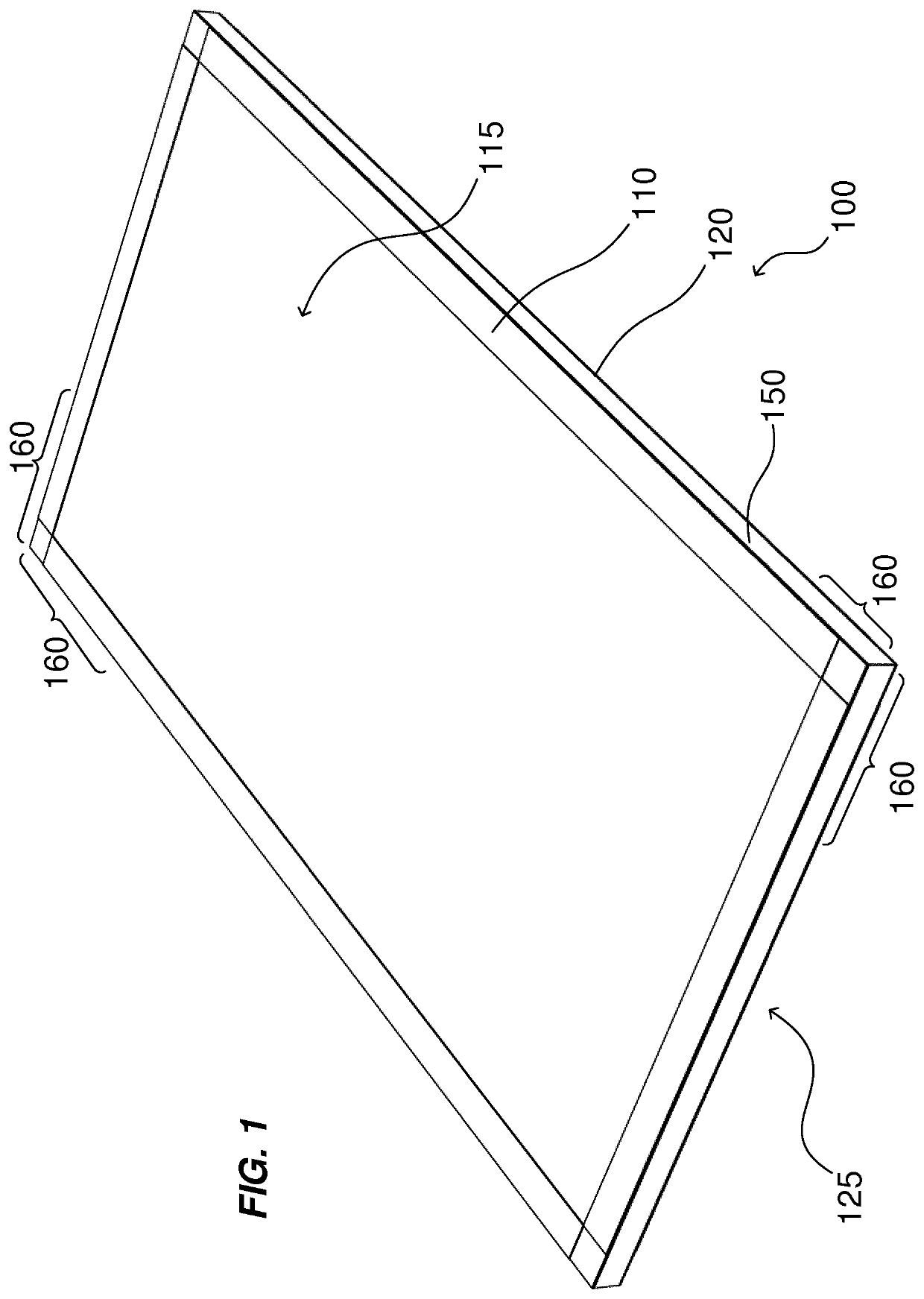
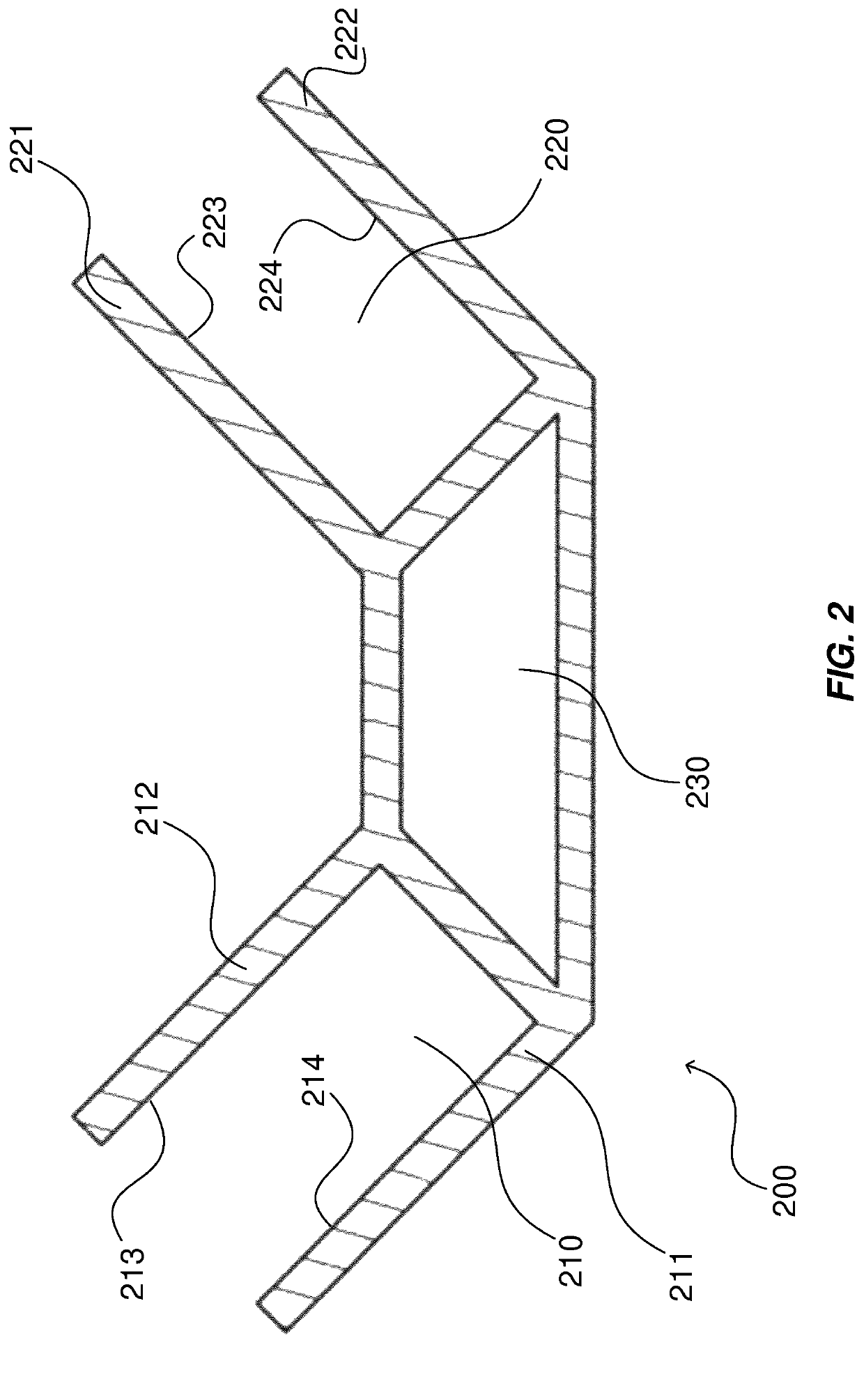
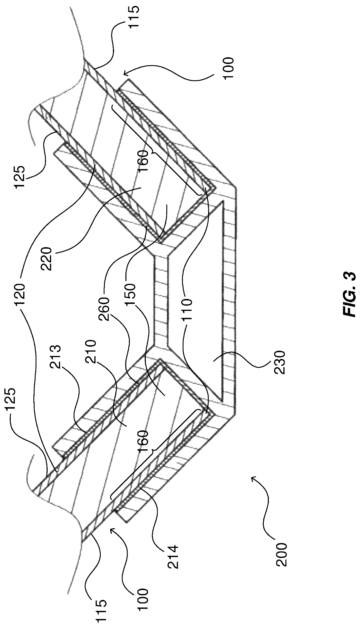
[0075]Chassis manufacture. In FIG. 1 is shown a rectangular bottom panel of polymer foam sandwiched between two sheets of a glass fibre reinforced thermoplastic polymer material. Rectangular profile joint mounting sections extend along the right and left lateral edges and the front and rear edges of the panel. At these sections profile joints for mounting right and left lateral panels and the front and rear panels are attached to the bottom panel (FIG. 4). The profile joints are of a length so as to extend short of a section at each corner of the bottom panel, which thus remains free. FIG. 2 illustrates a transverse section of a first variety of an extruded aluminium profile. Joints are made by a profile into sections of desired length. The profile has a central hollow trapezoid portion forming a channel and consists of a base section, a top section, and lateral sections. From the lateral sections extend in a perpendicular relationship outer and inner tongues forming rectangular sli...

example 2

[0079]First variety of profile joint. The profile joint of FIG. 2 can be varied in many ways. In a first variety of the joint shown in FIG. 7 the trapezoid central structure is substituted by a circular or tubiform structure comprising tongue bases extending in a tangential manner in an angle of 90°. The tongues extend in a perpendicular direction from the tongue bases. The lumen of the circular structure can be used for mounting external gear such as motor, suspension and wheels. A preferred manner of mounting external gear is by inserting coupling elements in form of steel rods or tubes into the lumen and fixing them there, which rods or tubes extend from one or both ends of the tubiform structure, thus are of a length greater than the length of the profile joint. It is, of course, possible to use the profile of FIG. 2 in a similar manner, the difference being that the insert into the trapezoid channel should preferably be of trapezoid or, less preferred, of rectangular form.

example 3

[0080]Second variety of profile joint. The profile joint illustrated in FIG. 8 in transverse section comprises a trapezoid central structure comprising top portion and lateral portions, from which tongues extend in a perpendicular direction forming slits in which panels are mounted and fixed with glue. In the trapezoid base is provided a central slit providing access into the lumen. Two L-formed, outwardly extending profile sections with their bases pointing towards each other are disposed laterally of the slit. They enclose a rectangular channel housing an insert of corresponding but slightly smaller rectangular section and of a length greater than the length of the profile joint thus extending from one or both ends of the joint. The insert is kept in place by one screw or several screws of same kind. The screw is inserted through the opening between the L-formed fingers and fixed in threaded bore of the insert, which is kept in place by being pressed against inner faces of the L-f...


PUM


Abstract

The present disclosure relates to a chassis (300) for a vehicle, the chassis (300) comprising a plurality of sandwich plate elements (100) and a plurality of connection elements (200), wherein the sandwich plate elements (100) each comprise a plate core (150) and a first and second plate skin (110, 120) and wherein each connection element (200) comprises two or more recesses (210, 220), each recess (210, 220) being adapted to receive an edge portion (160) of one of the plurality of sandwich plate elements (100) such that at least a portion of the sandwich plate element (100) interacts with the recess (210, 220), thereby connecting said plurality of sandwich plate elements (100) to form said chassis (300). The disclosure also relates to a vehicle comprising a chassis (300), a method for forming a chassis (300) and a kit of parts for assembling a chassis (300).

Description

CROSS-REFERENCE TO RELATED APPLICATIONS[0001]This application claims priority to International Application No. PCT / EP2017 / 078594, filed Nov. 8, 2017 and titled “CHASSIS FOR A VEHICLE,” which in turn claims priority from a Swedish Application having serial number 1600313-9, filed Nov. 9, 2016, and titled “CHASSIS FOR A VEHICLE,” both of which are incorporated herein by reference in their entireties.FIELD OF INVENTION[0002]The present disclosure relates to a chassis for a vehicle. It also relates to a vehicle comprising a chassis, a method for forming a chassis and a kit of parts for assembling a chassis for a vehicle.TECHNICAL BACKGROUND[0003]Within the field of vehicle construction, vehicles are universally built around chassis. The chassis distributes tensile and compressive forces throughout itself, contributing to the vehicle's stiffness and torsional stiffness. Very rigid chassis can be formed as monocoque chassis—the name implies that they are formed as “one body”. Such chassis...

Claims


Application Information

Patent Timeline
Patent Type & Authority Patents(United States)
IPC IPC(8): B62D21/10B62D29/00B62D29/04B62D65/02B62D23/00B62D27/02
CPCB62D21/10B62D23/005B62D27/026B62D29/008B62D29/046B62D29/048B62D65/024
Inventor LUTZ, HÅKAN GLANTON
Owner LUVLY AB
Learn More