Steam turbine system

a steam turbine and steam technology, applied in the direction of machines/engines, mechanical equipment, non-positive displacement engines, etc., can solve the problems of inability to cope with the fluctuation of the pressure of the steam supplied, and the steam does not easily flow into the steam turbine, so as to achieve smooth steam supply and efficient operation

Active Publication Date: 2021-11-02
MITSUBISHI HEAVY INDUSTIES COMPRESSOR CORP
View PDF16 Cites 0 Cited by
  • Summary
  • Abstract
  • Description
  • Claims
  • Application Information

AI Technical Summary

Benefits of technology

[0008]According to such a configuration, it is possible to adjust whether a steam supply destination is the upstream stage or the downstream stage on the basis of the differential pressure between the pressure of the steam supplied from the steam supply source and the pressure in the upstream stage. In a case where the differential pressure between the pressure of the steam supplied from the steam supply source and the pressure within the casing in the upstream stage is small, the steam does not easily flow into the upstream stage. The pressure within the casing in the downstream stage is lower than that in the upstream stage. Thus, in the downstream stage, the differential pressure between the pressure of the steam supplied from the steam supply source is larger than that in the upstream stage. Hence, if the steam is supplied to the downstream stage, the steam easily flows into the casing. On the other hand, in a case where the differential pressure between the pressure of the steam supplied from the steam supply source and the pressure within the casing in the upstream stage is sufficiently large, the steam easily flows into the upstream stage. In this case, by supplying the steam to the upstream stage on the upstream side of the downstream stage, the amount of work of the steam within the casing can be increased and the efficiency of the operation can be enhanced. In this way, even if the pressure of the mixed steam supplied from the mixed steam source fluctuates, it is possible to smoothly perform the supply of the mixed steam and to perform the efficient operation.
[0010]By adopting such a configuration, by closing the valve, the steam does not easily flow to the second mixed steam supply pipe, and the steam from the steam supply source is supplied to the upstream stage through the first mixed steam supply pipe. Conversely, by opening the valve, the steam from the steam supply source is supplied to the downstream stage with low pressure through the second mixed steam supply pipe. In this way, by virtue of a simple configuration including the valve, switching of the steam supply destination based on the differential pressure can be easily performed. As a result, the function of adjusting the flow rate of the steam supplied to the upstream stage and the downstream stage in the adjusting unit can be easily realized.
[0014]By adopting such a configuration, a case where the differential pressure between the pressure of the steam supplied from the steam supply source and the pressure within the casing in the upstream stage is small and the steam does not easily flow into the upstream stage can be appropriately determined. Then, the steam supply destination is switched from the upstream stage to the downstream stage. As a result, the steam can be supplied to the downstream stage and the mixed steam can be caused to efficiently continue flowing into the casing.
[0016]By adopting such a configuration, it is possible to reliably secure a differential pressure required to supply the steam of the flow rate into the casing depending on the flow rate of the steam supplied from the steam supply source. Accordingly, the steam supplied from a steam supply source can be caused to smoothly flow (supplied) into the casing.
[0017]According to the invention, even if the pressure of the steam supplied from the steam supply source fluctuates, it is possible to smoothly perform the supply of the steam to perform the efficient operation.

Problems solved by technology

If the differential pressure between the pressure of the steam supplied from the steam supply source and the pressure within the steam turbine is small, the steam does not easily flow into the steam turbine.
H09-303109 in which the switching of the mixed steam port is performed depending on the internal pressure of the turbine, it is not possible to cope with the fluctuation of the pressure of the steam supplied from the steam supply source.

Method used


Image

  • Steam turbine system
  • Steam turbine system
  • Steam turbine system

Examples


Embodiment Construction

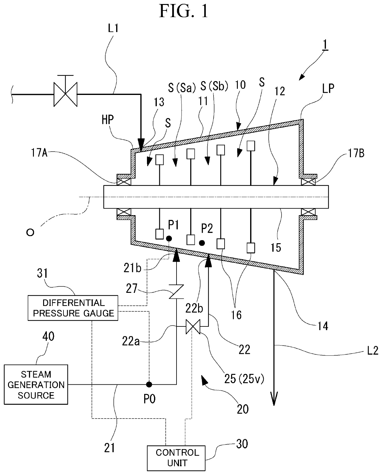
[0023]Hereinafter, an embodiment for carrying out a steam turbine system according to the invention will be described with reference to the accompanying drawings. However, the invention is not limited only to the embodiment. FIG. 1 is a view showing a schematic configuration of the steam turbine system in the embodiment of the invention. As shown in FIG. 1, the steam turbine system 1 mainly includes a steam turbine 10, a mixed steam supply unit 20, and a control unit 30.

[0024]The steam turbine 10 includes a casing 11 and a rotor 12. The casing 11 has a tubular shape that extends in the direction of a central axis O in which the central axis O of the rotor 12 extends. The casing 11 includes a steam inlet 13 provided on one side (a first side, an upstream side) in the direction of the central axis O, and a steam outlet 14 provided on the other side (a second side, a downstream side) in the direction of the central axis O. A steam supply line L1 is connected to the steam inlet 13. The ...


PUM


Abstract

A steam turbine system 1 includes a steam turbine 10 including a plurality of rotor blades 16; a first mixed steam supply pipe 21 that supplies the steam, which is supplied from a steam supply source 40 capable of supplying the steam with fluctuating pressure, to an upstream stage Sa within the casing 11; a second mixed steam supply pipe 22 that supplies the steam to the second stepped part Sb; an adjusting unit 25 that adjusts a flow rate of the steam supplied to the first stepped part Sa and the second stepped part Sb; and a control unit 30 that controls the adjusting unit 25 on the basis of a differential pressure between a pressure P0 of the steam supplied from the steam supply source 40 and a pressure in the first stepped part Sa.

Description

BACKGROUND OF THE INVENTIONField of the Invention[0001]The present invention relates to a steam turbine system.[0002]Priority is claimed on Japanese Patent Application No. 2019-014632, filed Jan. 30, 2019, the content of which is incorporated herein by reference.Description of Related Art[0003]In steam turbines, some steam turbines supply steam (mixed steam) thereinto separately from main steam. For example, Japanese Unexamined Patent Application Publication No. H09-303109 discloses a configuration in which a plurality of mixed steam ports connected to a mixed steam source are separately provided on an upstream side and a downstream side of a steam turbine. In this configuration, during a low-load operation in which the internal pressure of the turbine is low, mixed steam is supplied from a mixed steam port on a high-pressure side on the upstream side. During a high-load operation in which the internal pressure of the turbine is high, the mixed steam is supplied from a mixed steam p...

Claims


Application Information

Patent Timeline
Patent Type & Authority Patents(United States)
IPC IPC(8): F01D1/02F01D17/20F01D25/24
CPCF01D1/023F01D17/20F01D25/24F05B2260/233F05D2220/31F05D2270/301F01K7/20Y02P80/15
Inventor KODA, TAKUROSUGIMOTO, KAZUAKIKUNIMOTO, AKITONOGAMI, TOMOAKI
Owner MITSUBISHI HEAVY INDUSTIES COMPRESSOR CORP
Why Eureka
Try Eureka