Miniature brake and method of assembly

a technology of brakes and brake components, applied in the field of electric brakes, can solve the problems of limiting the size of the brake and the amount of brake torque that can be generated, and achieve the effects of preventing contamination of friction surfaces, high torque, and efficient assembly of the brak

Active Publication Date: 2021-11-16
WARNER ELECTRIC TECH
View PDF18 Cites 2 Cited by
  • Summary
  • Abstract
  • Description
  • Claims
  • Application Information

AI Technical Summary

Benefits of technology

[0007]A brake and method of assembling a brake in accordance with the present teachings are advantageous relative to conventional brakes and methods of assembly. In particular, the brake described herein is made without the use of conventional fasteners. As a result, the brake can be made relatively small while retaining sufficient size for electromagnetic components of the brake in order to generate a relatively high level of torque. The elimination of conventional fasteners also enables more efficient assembly of the brake and prevents contamination of friction surfaces in the brake with thread locking adhesives that are often used with conventional fasteners. The brake described herein also enables a precise air gap between the armature plate and electromagnet to be established during assembly by removing the impact of a tolerance stackup of the brake components.

Problems solved by technology

Certain applications, however, require brakes that are relatively small and conventional fasteners often limit how small the brake can be made.
Further, the space in the brake required by conventional fasteners limits the potential size of the electromagnetic components of the brake and, therefore, the brake torque that can be generated.

Method used


Image

  • Miniature brake and method of assembly
  • Miniature brake and method of assembly

Examples


Embodiment Construction

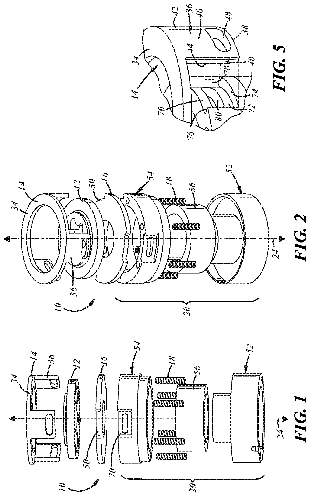
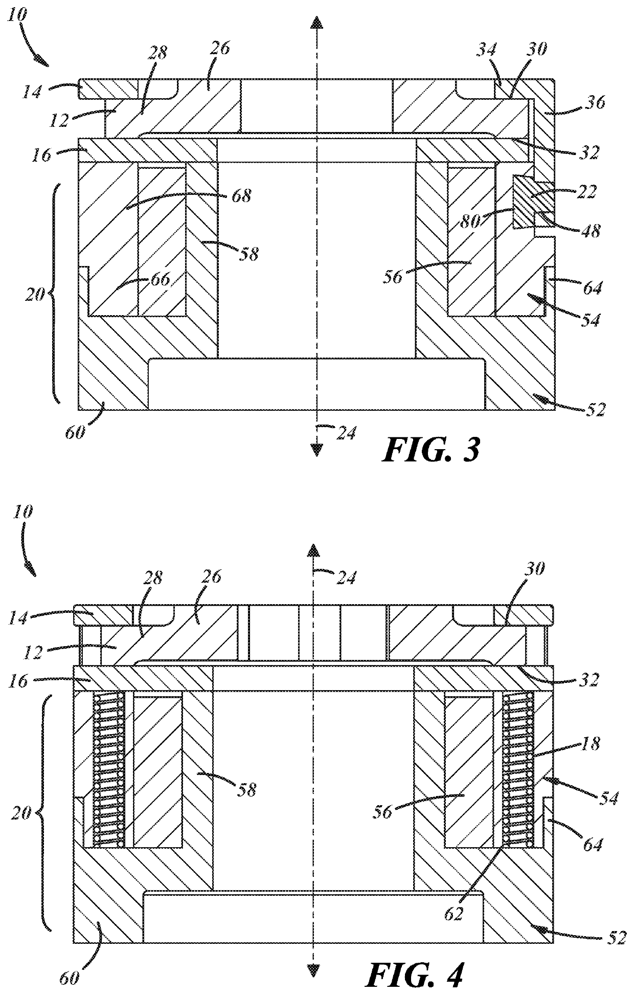
[0012]Referring now to the drawings wherein like reference numerals are used to identify identical components in the various views, FIG. 1-4 illustrate a brake 10 in accordance with one embodiment of the invention. Brake 10 provides a braking torque to a rotatable body such as a shaft, gear, pulley, blade, etc. in order to slow or halt rotation of a rotating body or to prevent rotation of a stationary body (i.e., a parking brake). It will be understood by those of ordinary skill in the art that brake 10 may be used in a wide variety of industrial and other applications requiring a brake. Brake 10 may include a friction plate 12, a pressure plate 14, an armature plate 16, means, such as springs 18, for biasing armature plate 16 in one direction, and means, such as electromagnet 20, for urging armature plate 16 in another direction. Referring to FIG. 3, in accordance with one aspect of the present teachings, brake 10 may also include one or more fasteners 22 used to couple the pressur...


PUM


Abstract

A brake and method of assembly are provided. The brake includes a friction plate configured for coupling to a rotatable body for rotation with the rotatable body about an axis of rotation, a pressure plate disposed about the axis on a first side of the friction plate and fixed against rotation, and an armature plate disposed about the axis on a second side of the friction plate. An electromagnet is disposed about the axis on an opposite side of the armature plate relative to the friction plate. A spring biases the armature plate in a first axial direction towards the friction plate and away from the electromagnet to engage the brake. A fastener couples the pressure plate to the electromagnet. The fastener conforms to a space between opposed surfaces of the pressure plate and the electromagnet and, upon hardening, bonds the pressure plate to the electromagnet.

Description

BACKGROUND OF THE INVENTIONa. Field of the Invention[0001]This disclosure relates to an electromagnetic brake. In particular, the instant disclosure relates to an electromagnetic brake in which components are joined without the use of conventional fasteners to facilitate manufacture of a relatively small brake that is capable of generating a relatively high level of braking torque.b. Background Art[0002]In conventional electromagnetic brakes, brake components are coupled together using threaded fasteners, bolts, pins, swaging and / or press fits. Certain applications, however, require brakes that are relatively small and conventional fasteners often limit how small the brake can be made. In particular, conventional fasteners generally must remain large enough to enable easy handling and assembly of the brake. Further, the space in the brake required by conventional fasteners limits the potential size of the electromagnetic components of the brake and, therefore, the brake torque that ...

Claims


Application Information

Patent Timeline
Patent Type & Authority Patents(United States)
IPC IPC(8): F16D59/02F16D65/00F16D63/00F16D121/20
CPCF16D65/0043F16D59/02F16D63/002F16D65/005F16D2121/20F16D65/04F16D65/14F16D2250/0084
Inventor MITELMAN, YURIYMELLOR, PATRICIA M.
Owner WARNER ELECTRIC TECH
Why Eureka
Try Eureka