System and a method for determining a trajectory to be followed by an agricultural work vehicle
a technology for agricultural work and a system, applied in the direction of vehicle position/course/altitude control, process and machine control, instruments, etc., can solve the problems of excessive time consumption, weight gain, and weight loss in the working operation, and achieve the effect of improving efficiency
- Summary
- Abstract
- Description
- Claims
- Application Information
AI Technical Summary
Benefits of technology
Problems solved by technology
Method used
Image
Examples
example 1
[0160]The following example discloses in detail one way of performing the mathematical operations necessary in the process of going from a field boundary to creating possible individual candidate trajectories and the step of assigning an efficiency parameter to each of those candidate trajectories so that the most efficient candidate trajectory can be chosen as the optimum trajectory when working that field with an agricultural working vehicle or implement.
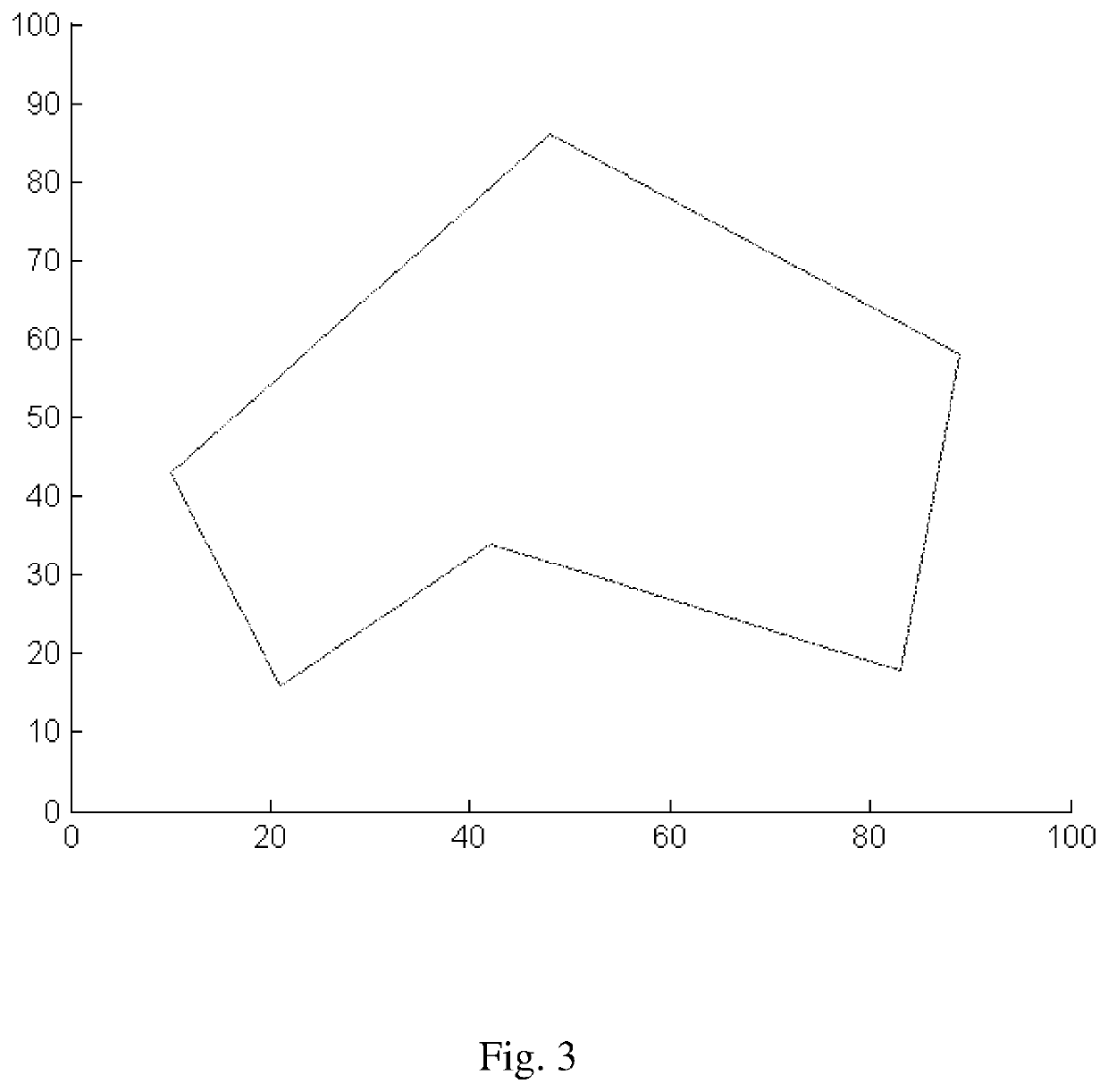
[0161]The present example is based on the principle involving the following steps:[0162]a) approximating the coordinates relating to the boundaries of the field to be worked to a boundary polygon;[0163]b) approximating the coordinates relating to the boundaries of each of the one or more obstacles, to respective obstacle polygons;[0164]c) defining one or more headlands located immediately within the boundary polygon;[0165]d) in respect of each obstacle polygon, defining one or more headlands surrounding the obstacle polygon;[0166]...
example 2
[0308]This example illustrates the present disclosure. This example illustrates in a very simplified and idealized way how the disclosure is to be conducted.
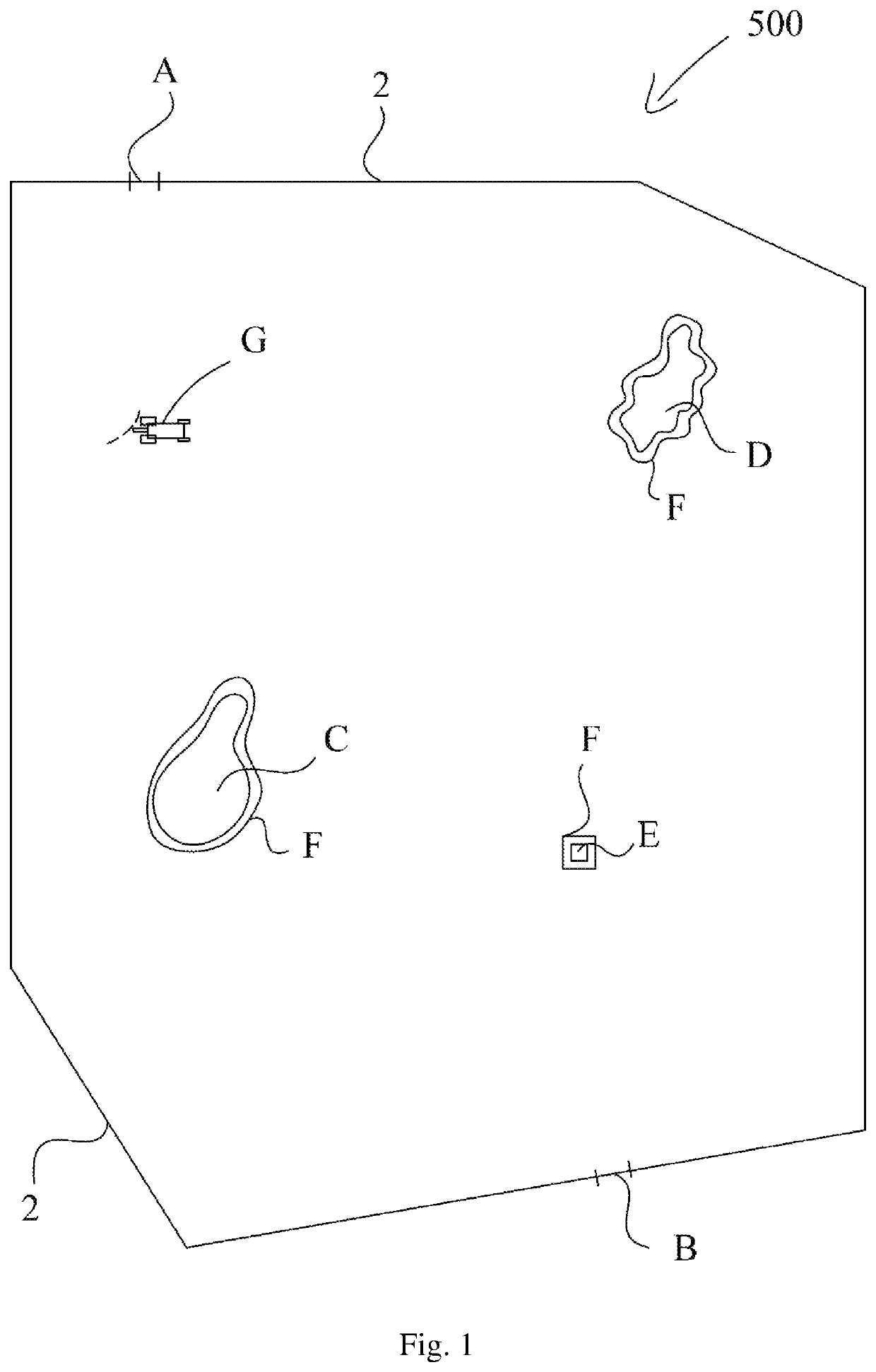
[0309]In this example, an agricultural field comprising a number of obstacles needs to be worked by an agricultural working vehicle or implement.
[0310]FIG. 24 illustrates the field to work. The field 500 is constrained within a field boundary 2. At a specific location on the field boundary 2 an entrance / exit gate 4 is located.
[0311]The field boundary comprises two pairs of parallel lines. In the lower right corner of the field shown in FIG. 24 two perpendicular boundary lines are connected by a circular path.
[0312]Within the field boundary 2, two obstacles 8, which obviously must be avoided when working the field, are located.
[0313]First, the field boundary 2 is approximated to the shape of a polygon. This is illustrated in FIG. 25.
[0314]FIG. 25 shows that the field boundary 2 of FIG. 24 has been approximated to a polygon. This ...
PUM
 Abstract
Description
Claims
Application Information
 - R&D
- Intellectual Property
- Life Sciences
- Materials
- Tech Scout
- Unparalleled Data Quality
- Higher Quality Content
- 60% Fewer Hallucinations
Browse by: Latest US Patents, China's latest patents, Technical Efficacy Thesaurus, Application Domain, Technology Topic, Popular Technical Reports.
© 2025 PatSnap. All rights reserved.Legal|Privacy policy|Modern Slavery Act Transparency Statement|Sitemap|About US| Contact US: help@patsnap.com


