
Supply device and method for producing a supply device

a supply device and supply device technology, applied in the direction of conveyors, transportation and packaging, conveyor parts, etc., can solve the problems of complex and elaborate bed replacement, complex handling, etc., and achieve the effect of simple bed production, easy production and assembly, and complex handling

Active Publication Date: 2021-12-14
INTERROLL HLDG
View PDF14 Cites 0 Cited by
  • Summary
  • Abstract
  • Description
  • Claims
  • Application Information

AI Technical Summary

Benefits of technology

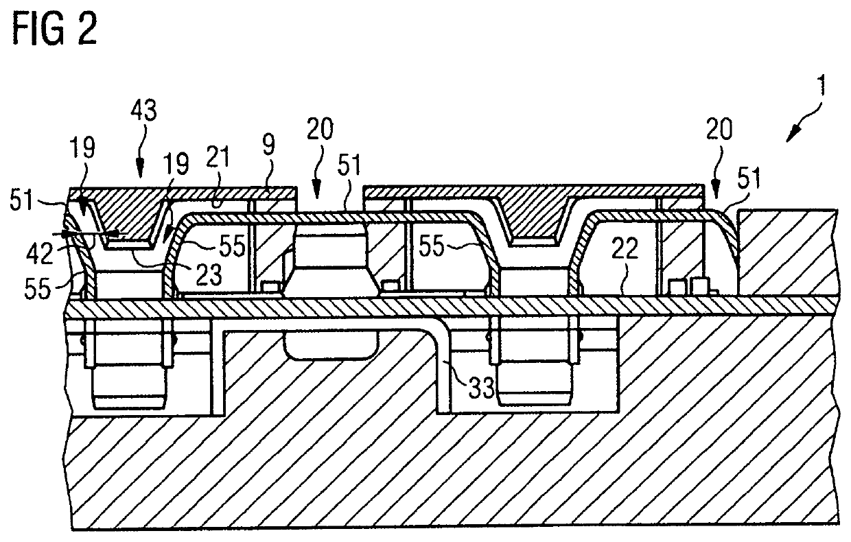
[0013]An advantage of the present invention lies with a simplified production of the bed. More particularly, the bed comprises multiple individual parts, compared to the bed usually contained in the above-mentioned known supply device. These individual parts can be easier to produce and assemble than a conventional bed, which, as mentioned, consists of one material block that needs to be processed elaborately and that is more complex in handling. Furthermore, in the event that one or multiple of the guiding devices are worn, the respectively worn guiding device can be replaced; replacing the entire bed is not necessary, and replacing only the worn bed is more cost-effective compared with the usually employed one-piece bed.
[0014]At least one lateral surface or at least one lateral wall of the guide groove can be provided and / or the guide groove can be delimited at least on one side by means of the guiding device. For example, each lateral surface or lateral wall can be formed by another guiding device, in particular of substantially the same construction.
[0015]The guide groove can be widened on at least one of its ends. For this purpose, in particular the cross-section of the guide groove can be wider on at least one end. Wear on the guide strip and / or to the element(s) forming the guide groove can be reduced thereby, in particular while the guide strip enters the guide groove and / or while the guide strip exits the guide groove.
[0016]For the widening of the guide groove, the at least one lateral surface or the at least one lateral wall of the guide groove can be inclined.
[0017]A base of the guide groove can be provided by the base table.
[0018]Advantageously, the at least one guiding device is attached to the base table in such a way that the guide groove is oriented approximately along the feed direction. As a result, a guiding, in particular a lateral guiding, of the respective conveyor belt is made possible.

Problems solved by technology

In some cases, this may come with several drawbacks, e.g. in that a blank for the bed has rather large dimensions, and thus handling a production of the bed is complex and elaborate.
In addition, when using multiple conveyor belts, there is a risk that the entire bed must be replaced in the case that only one or few of the guide grooves are worn.

Method used


Image

  • Supply device and method for producing a supply device
  • Supply device and method for producing a supply device
  • Supply device and method for producing a supply device

Examples


Embodiment Construction

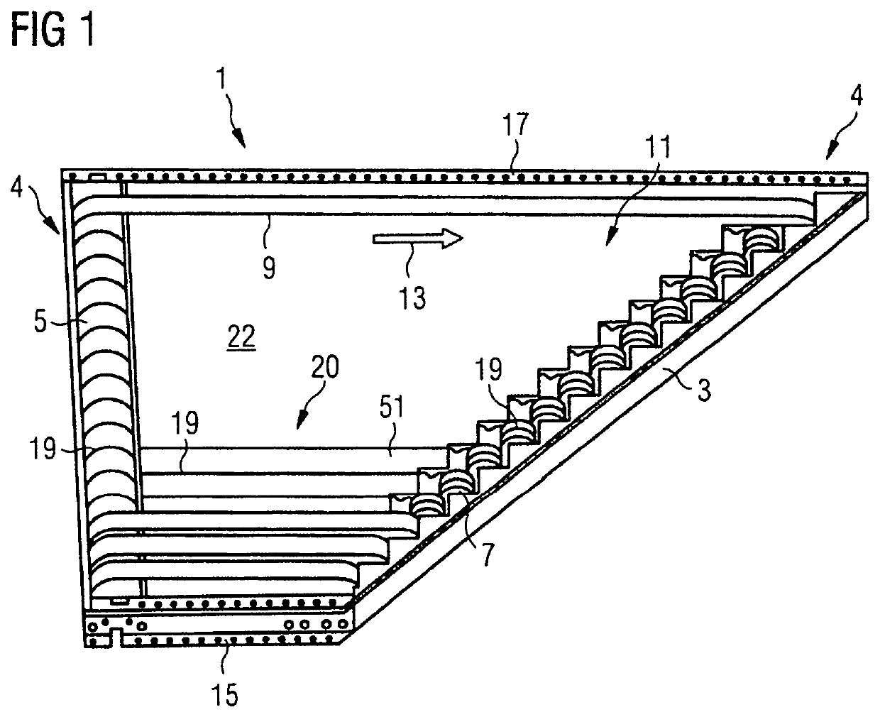
[0081]FIG. 1 shows a supply device 1 with a frame 3 and deflection pulleys 4, which, in the exemplary embodiment shown, are configured as a drive pulley 5 on the one side, and as a plurality of end pulleys 7 on the other side. In this embodiment, there are a total of 16 end pulleys 7. The supply device 1 comprises a base table 22 with two lateral end sections 15, 17. The axis of the drive pulley 5 is arranged substantially perpendicularly to these end sections 15, 17. The multiple end pulleys 7 are respectively associated with one conveyor belt 9—thus, in this exemplary embodiment, the supply device 1 comprises sixteen conveyor belts 9. A bed 11 is arranged between the drive pulley 5 and the end pulleys 7. Cover metal plates are arranged on the end pulleys 7, as a finger protection, attached to the frame 3. The supply device 1 for in particular lateral feeding of goods to be transported to a conveyor device can alternatively be used as a discharge device for discharging or guiding g...


PUM


Abstract

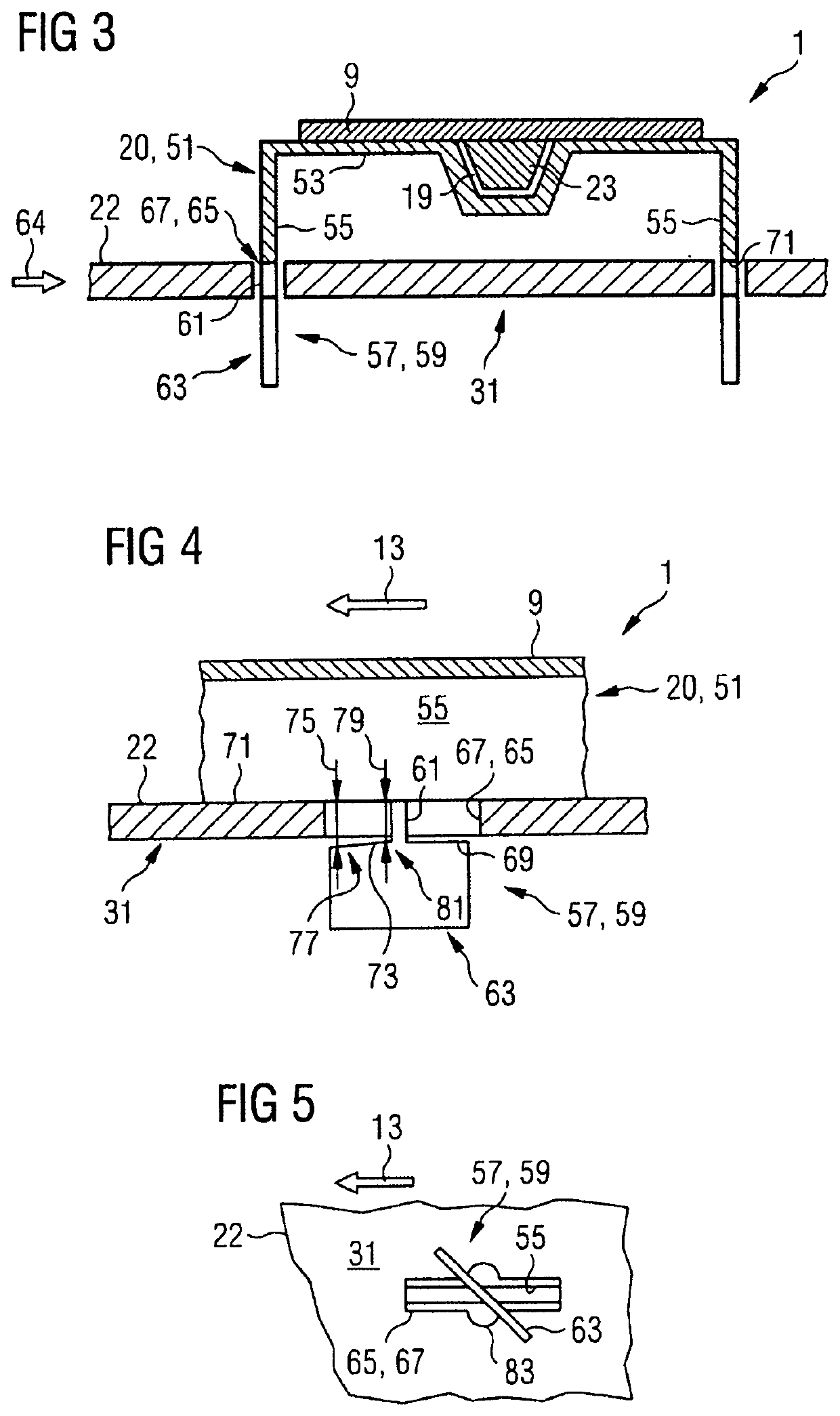
A supply device for feeding of goods to be transported to a conveyor device has at least one conveyor belt (9) that extends around two deflection pulleys (4) of the supply device. The at least one conveyor belt (9) has, on its inner side (21), a guide strip (23) arranged approximately along a feed direction (13), and has a bed (11) for guiding the at least one conveyor belt (9) between the two deflection pulleys (4) by a guide groove (19) for the guide strip (23). The bed (11) has a base table (22) and at least one guiding device (20) attached to the base table (22). The guide groove (19) is formed at least partially by the at least one guiding device (20).

Description

BACKGROUNDField of the Invention[0001]The invention relates to a supply device for lateral feeding or discharging of goods to be transported to a conveyor device, and to a method for providing a supply device for lateral feeding or discharging of goods to be transported to a conveyor device.Related Art[0002]The supply device of this type is used to supply goods to be transported laterally to a conveyor device. A known supply device has at least one conveyor belt that extends around two deflection pulleys, and a bed is arranged between the two deflection pulleys for guiding and / or supporting the at least one conveyor belt. The bed usually is formed in one piece with a guide groove formed therein for the guiding of the at least one conveyor belt, for example made of a plastic block with at least one guide groove milled into the bed. In some cases, this may come with several drawbacks, e.g. in that a blank for the bed has rather large dimensions, and thus handling a production of the b...

Claims


Application Information

Patent Timeline
Patent Type & Authority Patents(United States)
IPC IPC(8): B65G15/62B65G23/44B65G39/16B65G41/00B65G23/10
CPCB65G15/62B65G23/10B65G23/44B65G39/16B65G41/006B65G2201/02B65G2201/04B65G15/46
Inventor DUDEK, SIEGMUND
Owner INTERROLL HLDG
Learn More