Display device and surface light source
a technology of light source and display device, which is applied in the direction of instruments, non-linear optics, optics, etc., can solve the problem achieve the effect of reducing light transmission
- Summary
- Abstract
- Description
- Claims
- Application Information
AI Technical Summary
Benefits of technology
Problems solved by technology
Method used
Image
Examples
first embodiment
Effect of First Embodiment
[0056]In the first embodiment, the following effects can be achieved.
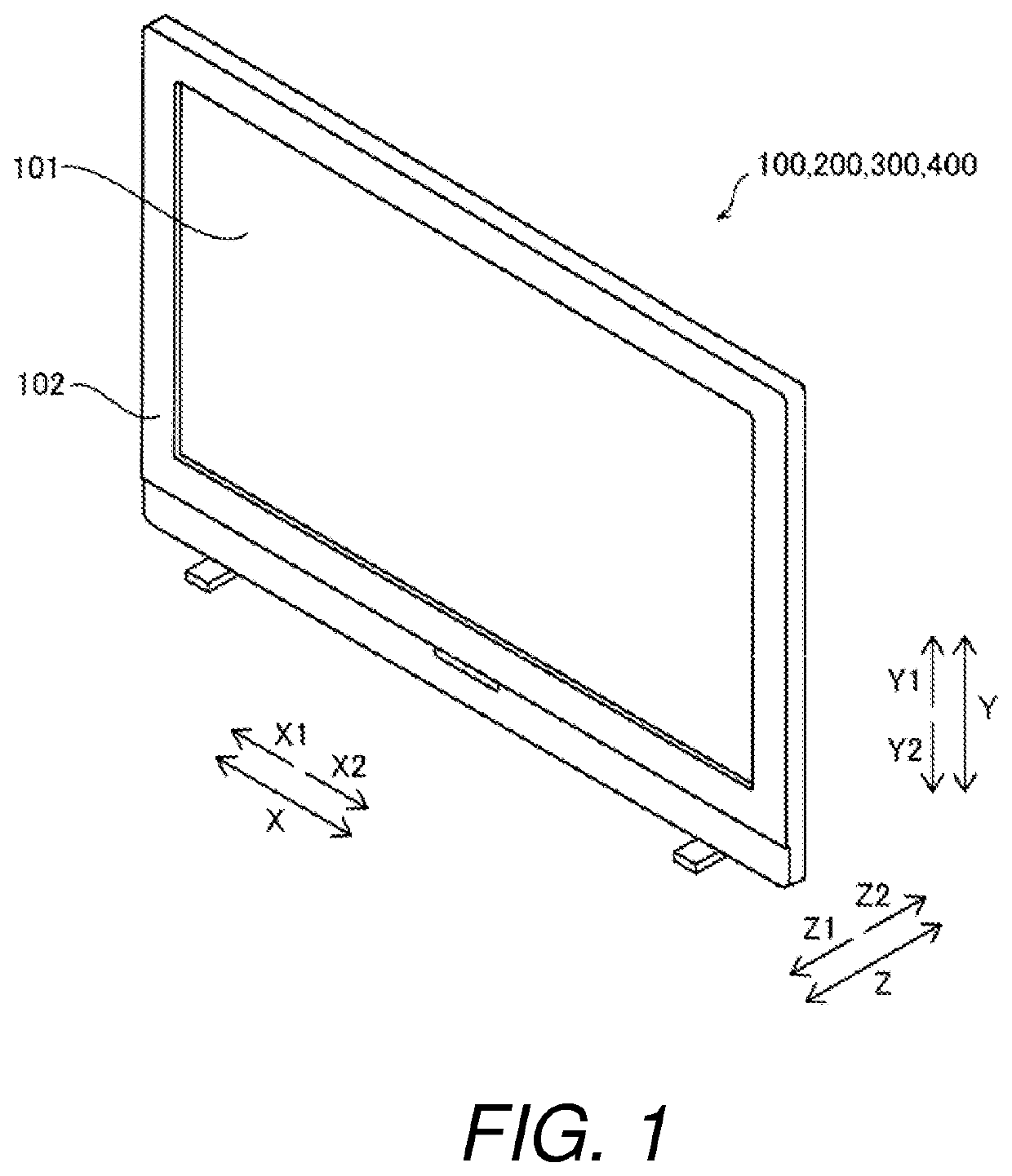
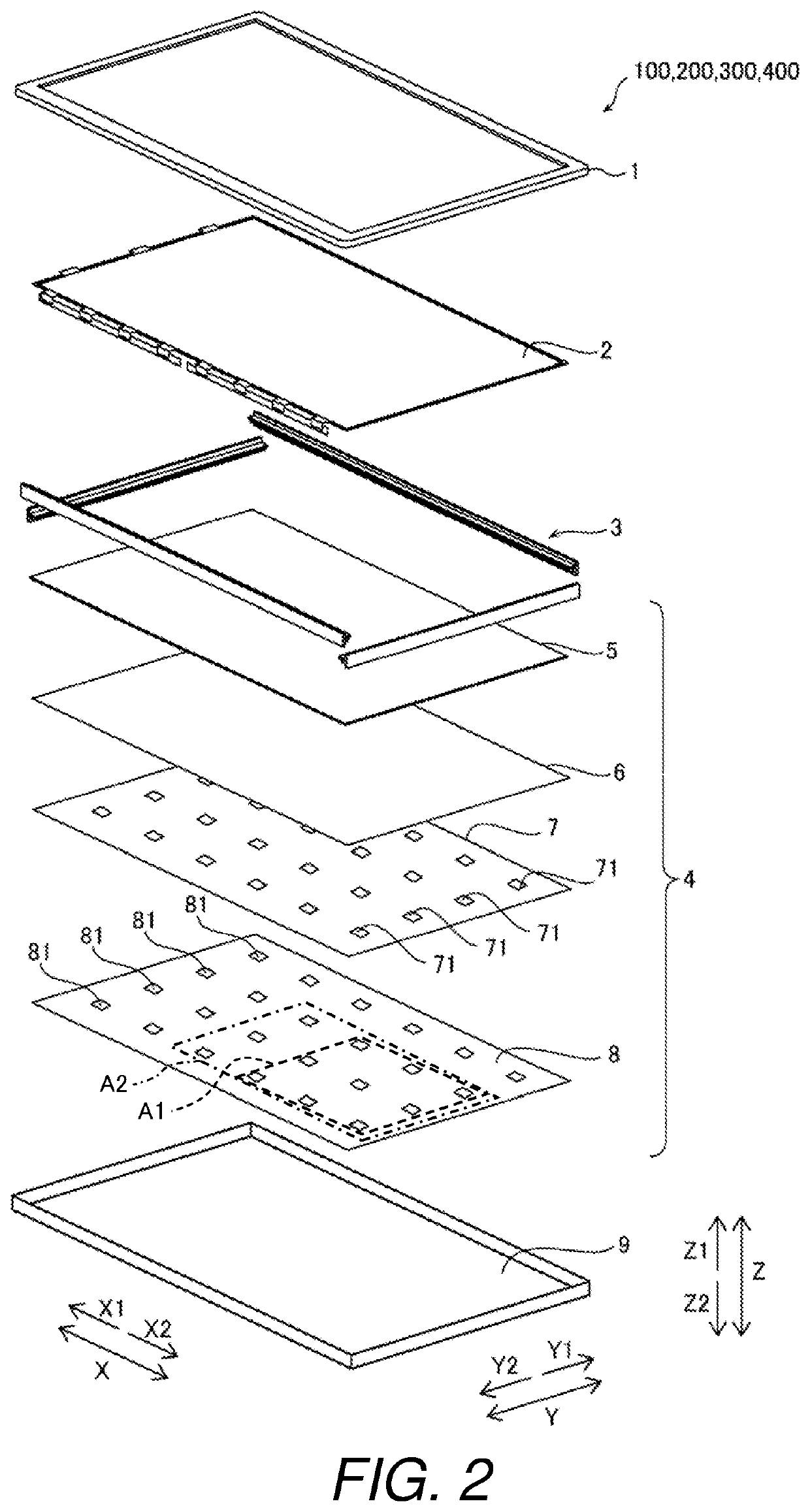
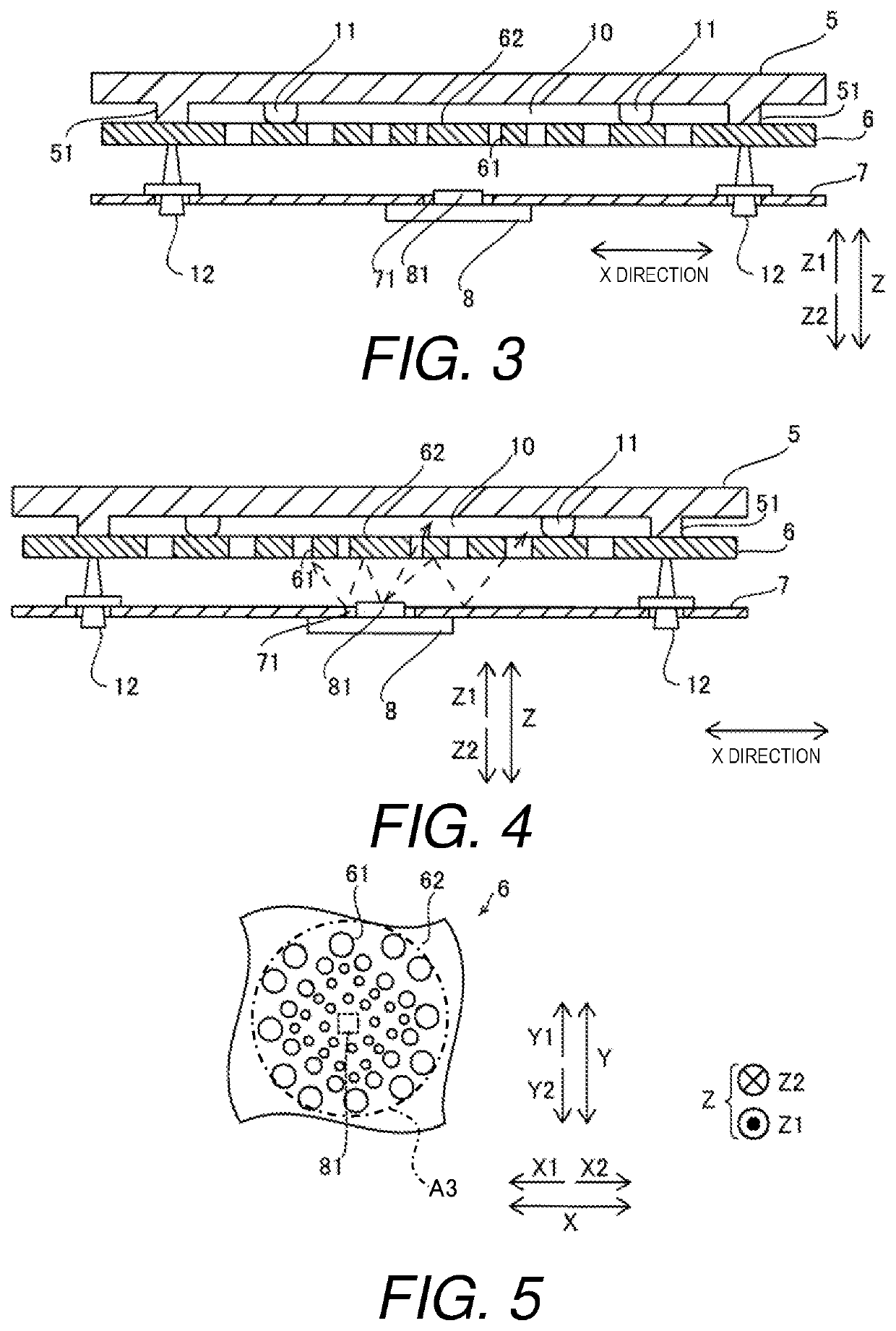
[0057]In the first embodiment, as described above, the liquid crystal television device 100 comprises the adhesive layers 11 bonding the optical member 6 and the diffusion plate 5 with the air layer 10 therebetween. The adhesive layers 11 are arranged spaced apart from each other in the direction in which the optical member 6 extends. The air layer 10 has the same thickness as the adhesive layers 11 and is located between the adjacent pairs of the adhesive layers 11. With this configuration, the optical member 6 is supported by the diffusion plate 5 by bonding the optical member 6 and the diffusion plate 5 via the adhesive layers 11. Thus, the optical member 6 can be prevented from deflecting even if a large number of support members 12 are not arranged. The adhesive layers 11 are arranged spaced apart from each other in the direction in which the optical member 6 extends, and the air laye...
second embodiment
Effect of Second Embodiment
[0072]In the second embodiment, as in the first embodiment above, the liquid crystal television device 200 comprises the adhesive layers 11 bonding the optical member 6 and the diffusion plate 5 with the air layer 10 therebetween. The adhesive layers 11 are arranged spaced apart from each other in the direction in which the optical member 6 extends. The air layer 10 has the same thickness as the adhesive layers 11 and is located between the adjacent pairs of the adhesive layers 11. With this configuration, the optical member 6 is supported by the diffusion plate 5 by bonding the optical member 6 and the diffusion plate 5 via the adhesive layers 11. Thus, the optical member 6 can be prevented from deflecting even if a large number of support members 12 are not arranged. The adhesive layers 11 are arranged spaced apart from each other in the direction in which the optical member 6 extends, and the air layer 10 between the optical member 6 and the diffusion p...
third embodiment
Effect of Third Embodiment
[0079]In the third embodiment, as in the first embodiment above, the liquid crystal television device 300 comprises the adhesive layers 11 bonding the optical member 6 and the diffusion plate 5 with the air layer 10 therebetween. The adhesive layers 11 are arranged spaced apart from each other in the direction in which the optical member 6 extends. The air layer 10 has the same thickness as the adhesive layers 11 and is located between the adjacent pairs of the adhesive layers 11. With this configuration, the optical member 6 is supported by the diffusion plate 5 by bonding the optical member 6 and the diffusion plate 5 via the adhesive layers 11. Thus, the optical member 6 can be prevented from deflecting even if a large number of support members 12 are not arranged. The adhesive layers 11 are arranged spaced apart from each other in the direction in which the optical member 6 extends, and the air layer 10 between the optical member 6 and the diffusion pla...
PUM
| Property | Measurement | Unit |
|---|---|---|
| thickness | aaaaa | aaaaa |
| thickness | aaaaa | aaaaa |
| thickness | aaaaa | aaaaa |
Abstract
Description
Claims
Application Information
 - R&D
- Intellectual Property
- Life Sciences
- Materials
- Tech Scout
- Unparalleled Data Quality
- Higher Quality Content
- 60% Fewer Hallucinations
Browse by: Latest US Patents, China's latest patents, Technical Efficacy Thesaurus, Application Domain, Technology Topic, Popular Technical Reports.
© 2025 PatSnap. All rights reserved.Legal|Privacy policy|Modern Slavery Act Transparency Statement|Sitemap|About US| Contact US: help@patsnap.com


